LINE SECTIONALIZING USING A PLC AND ABB PROTECTIVE RELAY
Page 11 of 53
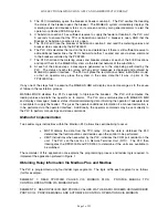
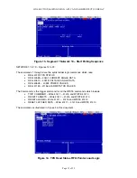
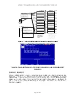
Figure 13. Segment 1 Network 10 – Start Polling Sequence
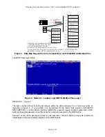
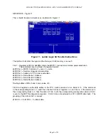
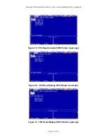
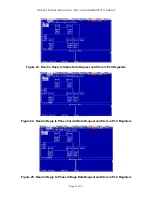
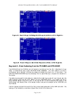
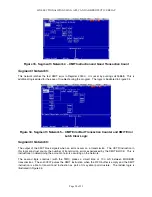
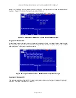
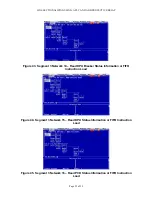
NETWORK 11 to 19 – Figures 14 to 22.
The commands 1 through 5 are the cyclic ladder logic commands which read
•
REG 40129 TPU STATUS
•
REG 40385 – 40401 CURRENT ANGLE DATA
•
REG 40513 – 40518 VOLTAGE ANGLE DATA
•
REG 40528 – 40533 POWER VALUES
•
REG 41153 –41156 ALARM STATUS VALUES
The Command 6 is the trigger command for all the WRITE commands which include
•
TRIP COMMAND – Write 41411 – 41415 and WRITE 41410
•
RESET TARGETS – Write 41411 – 41415 and WRITE 41410
•
RESET ALARMS – Write 41411 – 41415 and WRITE 41410
•
RESET LATCHED DATA – Write 41411 – 41415 and WRITE 41410
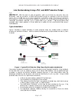
The commands as illustrated in Figure 3 of this document.
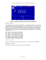
Figure 14. TPU Read Status FIFO Pointer Load Logic
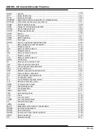
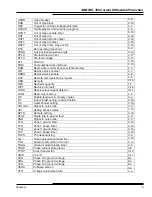
Summary of Contents for REL 356
Page 23: ...ABB REL 356 Current Differential Protection 1 10 Product Overview and Specifications ...
Page 83: ...ABB REL 356 Current Differential Protection 3 36 Settings and Application ...
Page 127: ...ABB REL 356 Current Differential Protection 5 28 Testing ...
Page 186: ...LINE SECTIONALIZING USING A PLC AND ABB PROTECTIVE RELAY Page 49 of 53 ...
Page 187: ...LINE SECTIONALIZING USING A PLC AND ABB PROTECTIVE RELAY Page 50 of 53 ...
Page 188: ...LINE SECTIONALIZING USING A PLC AND ABB PROTECTIVE RELAY Page 51 of 53 ...
Page 189: ...LINE SECTIONALIZING USING A PLC AND ABB PROTECTIVE RELAY Page 52 of 53 ...


