LINE SECTIONALIZING USING A PLC AND ABB PROTECTIVE RELAY
Page 14 of 53
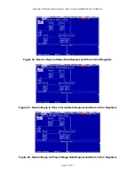
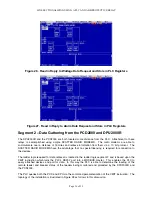
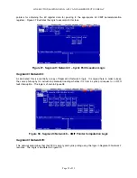
Figure 21. Reset Alarms FIFO Pointers Load Logic
Figure 22. Reset Latched Points FIFO Pointers Load Logic
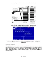
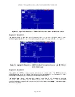
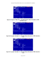
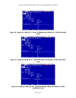
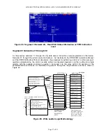
NETWORKS 20 to 24 – Figures 22 to 26
Once the data is read from the relay using the cyclic reads (pointers 1 through 5) or via the FIFO
commands, the data read must be transferred from the MSTR read buffer to a general buffer for retrieval
from the PLC. The PLC then serves as a data concentrator. The TPU data registers are contained in
41700 through 41726. The ladder logic networks in this construct are triggered when the MSTR
instruction has obtained the information from the relay. The instruction then transfers the appropriate
quantity to the appropriate registers (as illustrated by Figure 3 above).
The SUB instruction determines the MSTR command executed and the BLKM command instruction block
moves the information from the MSTR data buffer (40110) to the appropriate register location from 41700
through 41726 resident in the PLC.
Summary of Contents for REL 356
Page 23: ...ABB REL 356 Current Differential Protection 1 10 Product Overview and Specifications ...
Page 83: ...ABB REL 356 Current Differential Protection 3 36 Settings and Application ...
Page 127: ...ABB REL 356 Current Differential Protection 5 28 Testing ...
Page 186: ...LINE SECTIONALIZING USING A PLC AND ABB PROTECTIVE RELAY Page 49 of 53 ...
Page 187: ...LINE SECTIONALIZING USING A PLC AND ABB PROTECTIVE RELAY Page 50 of 53 ...
Page 188: ...LINE SECTIONALIZING USING A PLC AND ABB PROTECTIVE RELAY Page 51 of 53 ...
Page 189: ...LINE SECTIONALIZING USING A PLC AND ABB PROTECTIVE RELAY Page 52 of 53 ...

