LINE SECTIONALIZING USING A PLC AND ABB PROTECTIVE RELAY
Page 37 of 53
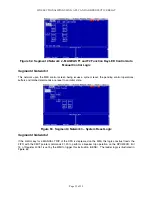
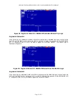
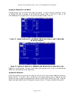
Segment 4 Networks 13 AND 14
The MMI displays data via bit data which toggles the graphics. The logic constructs in Networks 13 and
14 illustrate the logic to indicate on the display the breaker status of the TPU as well as the
AUTO/MANUAL PLC program control. The logic is illustrated in Figures 73 and 74.
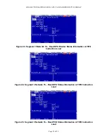
Figure 73. Segment 4 Network 13 - MAGELIS PCD Breaker Status Logic to Manipulate
the Screen Graphics
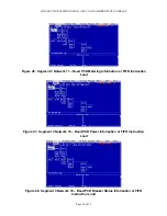
Figure 74. Segment 4 Network 12 - MAGELIS Auto Manual Screen Status Icon Logic
Segments 5 and 6 performs the logic which initiates the procedure upon a TPU monitored/protected
feeder trip. The explanation of the logic follows.
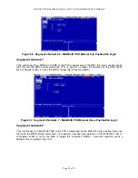
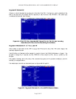
Segment 5 Network 1
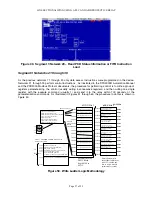
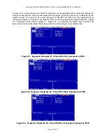
Since 52a and 52b are not direct points within the TPU, the PLC program reads WINDING currents for
phase A (41702) , B (41704) , and C (41706) and if the currents are less than 2 amperes, the TPU
denotes the relay as tripped and generated 52a (01201) and 52b (01202) internal status coils. Note that
labels have been affixed to each of the registers contacts and coils. The logic is illustrated in Figure 75.
Summary of Contents for REL 356
Page 23: ...ABB REL 356 Current Differential Protection 1 10 Product Overview and Specifications ...
Page 83: ...ABB REL 356 Current Differential Protection 3 36 Settings and Application ...
Page 127: ...ABB REL 356 Current Differential Protection 5 28 Testing ...
Page 186: ...LINE SECTIONALIZING USING A PLC AND ABB PROTECTIVE RELAY Page 49 of 53 ...
Page 187: ...LINE SECTIONALIZING USING A PLC AND ABB PROTECTIVE RELAY Page 50 of 53 ...
Page 188: ...LINE SECTIONALIZING USING A PLC AND ABB PROTECTIVE RELAY Page 51 of 53 ...
Page 189: ...LINE SECTIONALIZING USING A PLC AND ABB PROTECTIVE RELAY Page 52 of 53 ...


