LINE SECTIONALIZING USING A PLC AND ABB PROTECTIVE RELAY
Page 40 of 53
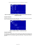
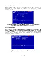
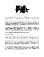
Segment 5 Network 6
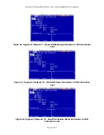
Since the TPU does not have 52a and 52b reported for a trip condition (since it is not wired into the
simulator in this example), if the current of each of the phases is a value less than 2 amps, the TPU is
determined to be tripped. This instruction construct sends a trip command (via the commands 6 and 7)
via the FIFO for the MSTR block. This trips the TPU to ensure the state of the unit. The network logic is
illustrated as per Figure 3 of this note. This network performs the action in MANUAL mode.
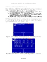
Figure 80. Segment 5 Network 6 – Trip TPU if Readings are Less Than 1 A Per Phase
(Since 52A and B Contacts are not Wired into Demo Case)
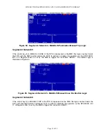
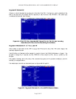
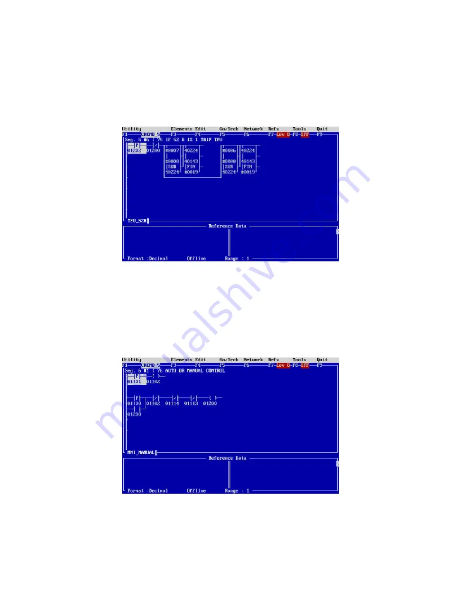
Segment 6 Network 1
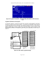
This network (although out of place in the scheme of things), takes a pushbutton input from the Magelis
MMI and places the PLC program in the MANUAL or AUTOMATIC restoration status. If coil 01200 is a
energized, the program is in AUTO mode. If the coil 01200 is de-energized, the program is in manual
mode. The logic is illustrated in Figure 81.
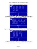
Figure 81. Segment 6 Network 1 – Upon MMI MAGELIS Action, Place the Program in
Manual or Automatic Restoration Mode
Summary of Contents for REL 356
Page 23: ...ABB REL 356 Current Differential Protection 1 10 Product Overview and Specifications ...
Page 83: ...ABB REL 356 Current Differential Protection 3 36 Settings and Application ...
Page 127: ...ABB REL 356 Current Differential Protection 5 28 Testing ...
Page 186: ...LINE SECTIONALIZING USING A PLC AND ABB PROTECTIVE RELAY Page 49 of 53 ...
Page 187: ...LINE SECTIONALIZING USING A PLC AND ABB PROTECTIVE RELAY Page 50 of 53 ...
Page 188: ...LINE SECTIONALIZING USING A PLC AND ABB PROTECTIVE RELAY Page 51 of 53 ...
Page 189: ...LINE SECTIONALIZING USING A PLC AND ABB PROTECTIVE RELAY Page 52 of 53 ...

