LINE SECTIONALIZING USING A PLC AND ABB PROTECTIVE RELAY
Page 41 of 53
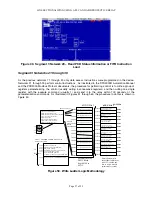
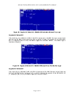
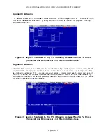
Segment 6 Network 2
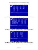
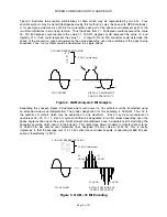
This network checks the TPU TARGET status which was stored in Register 41725. If a target is on the
front panel interface, an indication is given by coil 001150 which is used in this program. The logic is
illustrated in Figure 82.
Figure 82. Segment 5 Network 6 - Trip TPU if Reading are Less Than 1 A Per Phase
(Since 52A and B Contacts are not Wired into Demo Case)
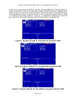
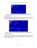
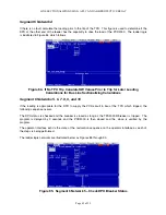
Segment 6 Network 3
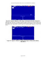
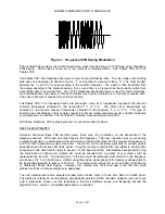
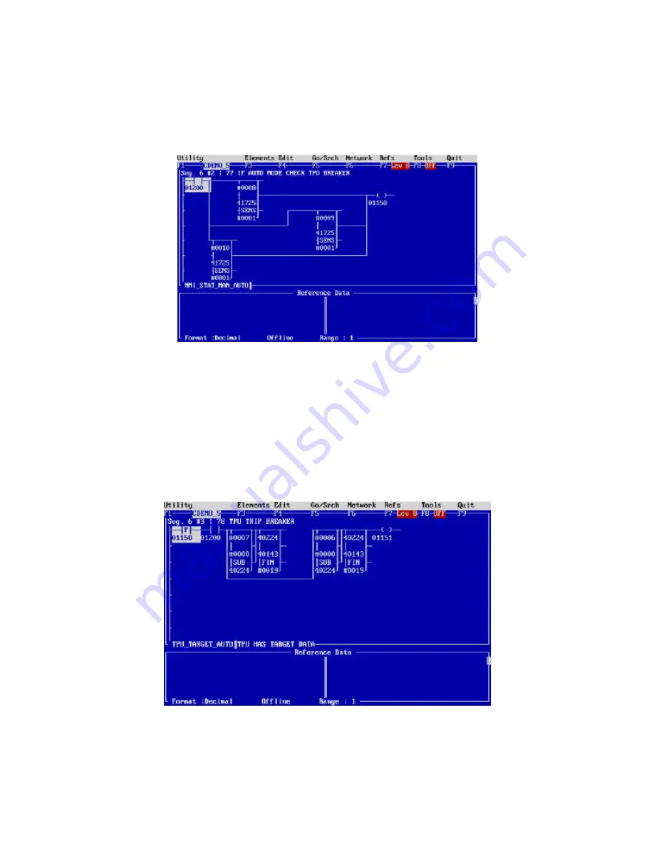
Since the TPU does not have 52a and 52b reported for a trip condition (since it is not wired into the
simulator in this example), if the current of each of the phases is a value less than 2 amps, the TPU is
determined to be tripped. This instruction construct sends a trip command (via the commands 6 and 7)
via the FIFO for the MSTR block. This trips the TPU to ensure the state of the unit. The network logic is
illustrated in Figure 83. This network performs the action in AUTOMATIC mode. The coil 01151 carries
this action to the next instruction network.
Figure 83. Segment 5 Network 6 - Trip TPU if Reading are Less Than 1 A Per Phase
(Since 52A and B Contacts are not Wired into Demo Case)
Summary of Contents for REL 356
Page 23: ...ABB REL 356 Current Differential Protection 1 10 Product Overview and Specifications ...
Page 83: ...ABB REL 356 Current Differential Protection 3 36 Settings and Application ...
Page 127: ...ABB REL 356 Current Differential Protection 5 28 Testing ...
Page 186: ...LINE SECTIONALIZING USING A PLC AND ABB PROTECTIVE RELAY Page 49 of 53 ...
Page 187: ...LINE SECTIONALIZING USING A PLC AND ABB PROTECTIVE RELAY Page 50 of 53 ...
Page 188: ...LINE SECTIONALIZING USING A PLC AND ABB PROTECTIVE RELAY Page 51 of 53 ...
Page 189: ...LINE SECTIONALIZING USING A PLC AND ABB PROTECTIVE RELAY Page 52 of 53 ...

