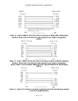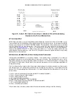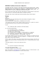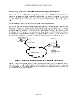
MODEM COMMUNICATION TO ABB RELAYS
Page 12 of 47
ZOOM 56Kx Dual Modem Faxmodem Configuration
The ZOOM modem offers more LED’s on their external modem than the US Robotics device. However,
the ZOOM modem must be configured for each parameter via a “TERMINAL EMULATOR” program. The
ZOOM modem does not offer a dipswitch for configuration of the different operation modes. AT “\”
commands and AT “X” (where X is a letter) performs the setup of the device.
Prior to configuring the modem, attach the proper cable between the terminal emulator and the modem.
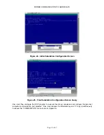
One Should Type “AT” (without the quotation marks) and depress the enter key.
If the modem does not answer, please check the terminal emulator settings to be the following:
9600 Baud
7 Data Bits
1 Stop
Even Parity
Hardware or No Flow Control depending upon the cable selected and configuration of modem.
VT 100 Terminal Emulation
Inbound Communications: Carriage Return = Carriage Return and Line Feed
If the modem does connect, then the following command may be sent to initialize the modem to
parameterize the RS232 com ports to the proper mode as explained below.
AT=&F0
&F0 = Initialize the modem to Hardware Control Factory Defaults.
AT = &C1 &D0 &G0 &K3 &Q0 &S0
&C = Carrier Detect Override (1 = Overridden)
&D = Data Terminal Ready Control (0= Overridden)
&G= Guard Tone (0 = USA & Canada)
& K = Local Flow Control (0 = Disabled, 3 = Hardware RTS/CTS, 4 = XON/XOFF)
&Q = Asynchronous Communication Mode (0 = Asynchronous Mode Buffered)
& S = Data Set Ready Operation (0 = DSR Overridden – Always ON)
For this modem, Register S0 controls the Auto-answer feature. Autoanswer is controlled via the dip-
switch position 5 and a combination of the value in register S0. To change the value of auto answer
pickup (number of rings) send the command:
ATS0= X, where X is the number of rings which the device shall sense for phone pickup. Note if the host
is to dial out the number at all times, this parameter may be set to a “0” thereby disabling the auto answer
feature.
To view the configuration, one may issue the following command:
AT=&V
&V = View Active Configuration and Stored Profile
This can view the programmed profiles.
To store this configuration, the command AT=&W0.
Refer to the document at
www.lucent.com
for an explanation of the AT “L” commands where L is the
defined commands for dial-up, speaker control, and other modem functions.
Summary of Contents for REL 356
Page 23: ...ABB REL 356 Current Differential Protection 1 10 Product Overview and Specifications ...
Page 83: ...ABB REL 356 Current Differential Protection 3 36 Settings and Application ...
Page 127: ...ABB REL 356 Current Differential Protection 5 28 Testing ...
Page 186: ...LINE SECTIONALIZING USING A PLC AND ABB PROTECTIVE RELAY Page 49 of 53 ...
Page 187: ...LINE SECTIONALIZING USING A PLC AND ABB PROTECTIVE RELAY Page 50 of 53 ...
Page 188: ...LINE SECTIONALIZING USING A PLC AND ABB PROTECTIVE RELAY Page 51 of 53 ...
Page 189: ...LINE SECTIONALIZING USING A PLC AND ABB PROTECTIVE RELAY Page 52 of 53 ...

