ABB REL 356 Current Differential Protection
1-8
Product Overview and Specifications
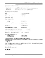
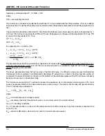
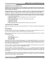
Operation is obtained when OP - 0.7 RES > OTH
where
OTH = set operating threshold
The worst case to consider is an external fault with one CT non-saturated while the other saturates. (This is an unlikely
case since the CT’s will have the same current and with similar characteristic and burden, both will have similar satura-
tion.)
One end will then deliver the undistorted ITL. The other end will deliver some lower value of current, corresponding to x%
of a “true” ITR. As this is an external fault ITR and ITL are 180 degrees out of phase and the magnitude of the “true” ITR
is equal to the magnitude of ITL. Thus:
TR
TL
TR
TL
xI
I
RES
xI
I
OP
+
=
−
+
=
)
(
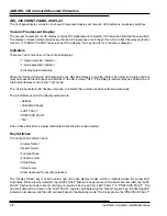
For operation OP
> 0.7 RES + OTH
TL
TL
TL
TL
TL
TL
TL
TR
TL
TR
TL
I
OTH
I
x
OTH
xI
I
xI
I
OTH
xI
I
xI
I
I
OTH
as
176
.
0
7
.
1
3
.
0
)
(
7
.
0
)
(
)
(
7
.
0
)
(
<<
≈
⋅
−
⋅
<
+
+
>
−
+
+
+
>
−
+
The example shows that for an external fault, operation will only take place if the saturated CT delivers less than 17.6%
current compared to true current. Even for the most severe saturation, a considerably higher amount current of funda-
mental frequency will be available.
The above example illustrates the high security of the REL 356 relay. It is difficult to derive an exact mathematical
formula due to the complexity in mathematically describing CT saturation as a factor of fault current and system dc
component. One important factor for the amount of saturation is the remanence present in the CT and this can not easily
be taken into account in a theoretical study.
The formula we are giving for CT verification is based on experience. As it is impossible to test all types of CTs for all
cases of remanence a factor 2 has been introduced as a safety margin. This means that the relay will operate correctly
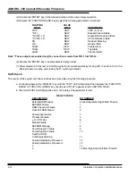
if the CT satisfies the requirement:
(
)
356
max
min
2
R
R
R
I
V
L
CT
k
k
+
+
⋅
=
where
V
kmin
= minimum knee-point voltage required
I
kmax
= secondary maximum through fault current, i.e. maximum current for an external fault
R
CT
= CT secondary resistance
R
L
= CT secondary burden, i.e. the sum of the cable resistance and the resistance of any other devices connected to the
same CT core
R
356
= burden of REL 356; 0.06 ohms for 1A and 0.02 ohms for 5A rated current
Summary of Contents for REL 356
Page 23: ...ABB REL 356 Current Differential Protection 1 10 Product Overview and Specifications ...
Page 83: ...ABB REL 356 Current Differential Protection 3 36 Settings and Application ...
Page 127: ...ABB REL 356 Current Differential Protection 5 28 Testing ...
Page 186: ...LINE SECTIONALIZING USING A PLC AND ABB PROTECTIVE RELAY Page 49 of 53 ...
Page 187: ...LINE SECTIONALIZING USING A PLC AND ABB PROTECTIVE RELAY Page 50 of 53 ...
Page 188: ...LINE SECTIONALIZING USING A PLC AND ABB PROTECTIVE RELAY Page 51 of 53 ...
Page 189: ...LINE SECTIONALIZING USING A PLC AND ABB PROTECTIVE RELAY Page 52 of 53 ...

