MODEM COMMUNICATION TO ABB RELAYS
Page 35 of 47
Example 4 – Connection of a REL512 ASCII Serial Port 2 (Rear Port) to
Hyperterminal Software
The REL512 has settings capabilities configurable and viewable via its rear com port (which is a DTE
RS232 port). Any dumb terminal emulator is able to connect to the rear port and synchronize with the
unit to allow visualization of the REL512 parameters. Within this example, two US Robotic model 002806
(V.EVERYTHING modem using trellis technology encoding [which differs from the QAM encoding]). As
illustrated in Figure 43, the modems are configured via a point to point connection. The REL512 ASCII
protocol is not addressable and therefore cannot be multi-dropped unless port switch devices are added
to the system. The steps to establish communications are:
1.
Connect the correct cable between the REL512 SERIAL 2 port and the modem.
2.
Connect the correct cable between the PC executing the HYPERTERMINAL program (in this
case the operating system used is Windows 95).
3.
Parameterize the REL512 rear port communication parameters.
4.
Set the jumpers internal to the relay for correct RS 232 port configuration
5.
Configure and set HYPERTERMINAL settings.
6.
Parameterize each US Robotics modem using its particular AT command set.
7.
Execute the connectivity procedure to establish communications.
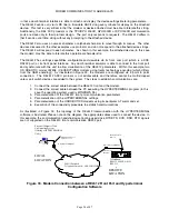
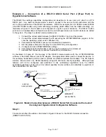
As illustrated in Figure 42, the topology of the REL512 interconnection with the HYPERTERMINAL
software is illustrated. Please note on the diagram, the appropriate cables used to connect the device. In
this example, handshaking will be used to provide coordination between the modems. The US Robotic
modems allow Carrier Loss Redial capability along with dial back security capability. Although these
features will not be configured and examined in this rudimentary application note, the RS232
handshaking features will be set up to its fullest capability to allow addition (and reliability in operation) of
these capabilities at a later date.
19200 Baud
REL Menu ASCII Protocol
REL 512
Public Switched
Telephone Network - ANALOG LINE
Personal Computer With
RCP Installed
10 Bit Dial Up MODEM
10 Bit Dial Up MODEM
Auto- Answer
Enabled
Example Cable 5-
Figures 11..
Example Cable 6 or 7
Figures 12 or 13.
ABB
ABB
ABB
ABB
ABB
LOCAL
LOCATION
REMOTE
LOCATION
Figure 42. Modem Connection between a REL512 Serial Port 2 (Located at the back of
the relay) and Hyperterminal Configuration Software
Step 1:
Construct and attach the cable as illustrated in Figure 42 above for the REL512/modem connection.
(REMOTE LOCATION).
Summary of Contents for REL 356
Page 23: ...ABB REL 356 Current Differential Protection 1 10 Product Overview and Specifications ...
Page 83: ...ABB REL 356 Current Differential Protection 3 36 Settings and Application ...
Page 127: ...ABB REL 356 Current Differential Protection 5 28 Testing ...
Page 186: ...LINE SECTIONALIZING USING A PLC AND ABB PROTECTIVE RELAY Page 49 of 53 ...
Page 187: ...LINE SECTIONALIZING USING A PLC AND ABB PROTECTIVE RELAY Page 50 of 53 ...
Page 188: ...LINE SECTIONALIZING USING A PLC AND ABB PROTECTIVE RELAY Page 51 of 53 ...
Page 189: ...LINE SECTIONALIZING USING A PLC AND ABB PROTECTIVE RELAY Page 52 of 53 ...


