MODEM COMMUNICATION TO ABB RELAYS
Page 39 of 47
21.
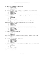
Depress the “E” key to accept the selections.
22.
Depress the “C” key to back out of the relay and accept the settings when prompted by the REAR
panel interface.
Step 4:
The REL512 Serial Port 2 is able to be configured for RS232 or RS485 connectivity. The configuration
procedure is achieved via jumpers located near the Serial Port 2 interface on the relay. The default
configuration for the relay is RS232. However one should verify jumper settings via the following
procedure:
1.
The technician performing this operation should be wearing anti-static wrist straps and work
on an anti-static environment to ensure that static electricitiy is not conducted between the
operator and REL512 internal components.
2.
Rotate the knurled screws to the left and right of the REL512, which secure the front panel
interface to the housing of the unit. The knurled screws should be turned counterclockwise
(or to the left) to loosen the screws.
3.
Remove the blue and red ribbon cable interconnecting the electronic signals between the
front panel interface and the REL512 motherboard. The internal assembly of the unit should
be visible.
4.
While grasping the internal assembly ejectors, and cantilevering the ejectors towards you,
remove the internal assembly board from the chassis.
5.
As illustrated, 5 jumpers are located near the rear serial port connector. The jumper locations
for RS232 and RS485 operation are listed in Table 2. Ensure that the jumpers placed in the
locations corresponding to the RS232 positions listed in the table.
6.
Place the board into the REL512 housing pressing the assembly ejectors with even force to
mate the connections within the assembly with the REL512 motherboard.
7.
Carefully reattach the blue and red ribbon cable interconnecting the electronic signals
between the front panel interface and the REL512 motherboard.
8.
With the front panel interface in the correct position, secure the front panel interface with the
housing by tightening the knurled screws on the left and right side of the panel. The screws
should be rotated clockwise (or to the right).
Step 5:
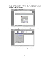
The operator should configure the HYPERTERMINAL settings to match those of the configuration made
for the REL512. The procedure is as follows:
1.
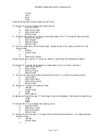
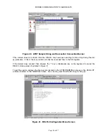
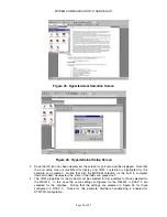
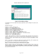
Select HYPERTERMINAL from the WINDOWS menu to reveal the following screen
illustrated in Figure 43.
2.
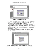
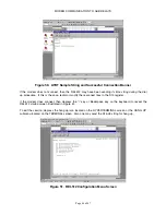
Select the icon labeled Hyperterminal.exe. The screen illustrated in Figure 44 should be
visible. The operator will be prompted for a name as illustrated.
Summary of Contents for REL 356
Page 23: ...ABB REL 356 Current Differential Protection 1 10 Product Overview and Specifications ...
Page 83: ...ABB REL 356 Current Differential Protection 3 36 Settings and Application ...
Page 127: ...ABB REL 356 Current Differential Protection 5 28 Testing ...
Page 186: ...LINE SECTIONALIZING USING A PLC AND ABB PROTECTIVE RELAY Page 49 of 53 ...
Page 187: ...LINE SECTIONALIZING USING A PLC AND ABB PROTECTIVE RELAY Page 50 of 53 ...
Page 188: ...LINE SECTIONALIZING USING A PLC AND ABB PROTECTIVE RELAY Page 51 of 53 ...
Page 189: ...LINE SECTIONALIZING USING A PLC AND ABB PROTECTIVE RELAY Page 52 of 53 ...


