ABB REL 356 Current Differential Protection
2-2
Installation, Operation and Maintenance
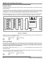
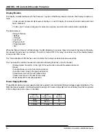
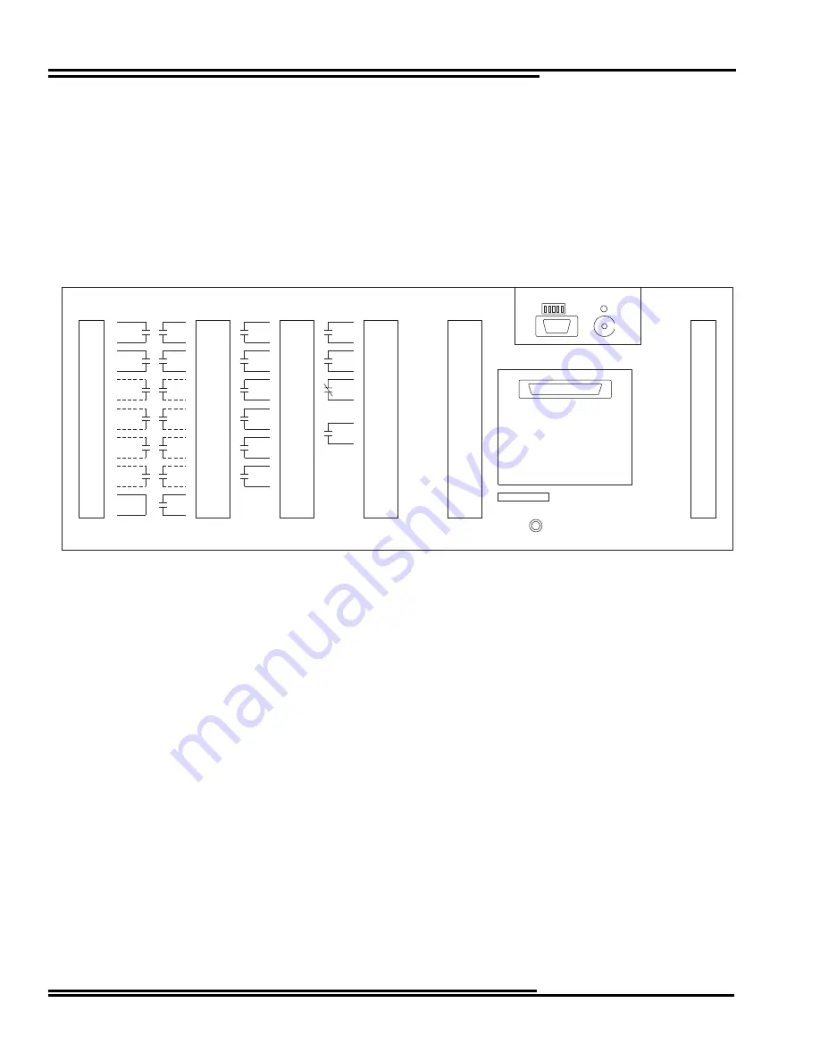
Backplane Module
The Backplane Assembly includes three voltage transformers, three current transformers, four filter chokes and surge
protection capacitors.
The Backplane Module receives all external connections and connects directly to the Interconnect module, thru plug-in
connectors (J11, J12, J13); and to the Relay Output and Contact Input modules, mounted on the Interconnect module
(via connectors JA1, JA2, JA3, JA4), which provide the connections between the inner and outer chassis.
Backplane Module provides connection to DCI module used for 56/64 kbps Digital Communications. The INCOM/PONI
®
is mounted on the Backplate of the outer chassis and is connected to the Backplane module (via connector J4).
Figure 2-1. Backplane
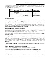
There are two jumpers on the backplane, JMP1 and JMP2. These jumpers are factory set for the communication option
included in the relay. The settings are as follows:
Audiotone version
Digital Communication
JMP1
TP1A
TP1D
JMP2
TP2A
TP2D
Interconnect Module
The Interconnect module becomes the floor of the REL 356 inner chassis; it provides electrical connections from and to
all other modules: from the Backplane (at the rear), to the Analog Input and Power Supply modules (at left and right,
respectively), to the Relay Output and Contact Input modules in the center, and to the Modem or CODEC, Microproces-
sor and Display modules at the front of the inner chassis.
The Interconnect module receives inputs V
AG
, V
B G
, V
CG
, I
A
, I
B
, I
C
from the Backplane module and feeds them to the
Analog Input module.
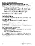
There are two jumpers on the interconnect board, JMP1 and JMP2. These jumpers are factory set for the communica-
tion option included in the relay. The settings are as follows:
Audiotone version
Digital Communication
JMP1
OUT
IN
JMP2
OUT
IN
1
2
TRIP
TRIP
TRIP
TRIP
TRIP
TRIP
3
4
5
6
7
8
9
10
11
12
13
14
BFI/RECL
ENABLE
BFI
1
2
BFI
3
4
BFI
5
6
BFI
7
8
BFI
9
10
BFI
11
12
13
14
RB-1
1
2
RB-2
3
4
RI1-1
5
6
RI1-2
7
8
RI2-1
9
10
RI2-1
11
12
GEN
START
13
14
TRP ALM
BKR1
1
2
TRP ALM
BKR2
3
4
FAILURE
ALARM
5
6
7
CHANNEL
ALARM
8
9
10
11
12
13
14
CHASSIS
GROUND
AUDIO COMM
XMIT OUT
AUDIO COMM
RCVR IN
1
2
3
4
5
6
7
8
9
10
14
13
12
11
(+)
52b
(-)
(+)
BKUP PROT
DISABLE
(-)
(+)
(-)
(+)
TARGET
RESET
(-)
(+)
DTT
KEY
(-)
(+)
STUB
BUS
(-)
(+)
DIFF PROT
DISABLE
(-)
DCI
DIGITAL COMMUNICATIONS INTERFACE
56/64 kB DIRECT DIGITAL INTFC
VA1
VB2
VC3
VN4
IAR5
IA6
IBR7
IB8
ICR9
IC10
1BP11
1BN12
2BP13
2BN14
GND
TB6
1FT-14
TB5
TB4
TB3
TB2
TB1
2FT-14
REL356
REL356XXXX
Summary of Contents for REL 356
Page 23: ...ABB REL 356 Current Differential Protection 1 10 Product Overview and Specifications ...
Page 83: ...ABB REL 356 Current Differential Protection 3 36 Settings and Application ...
Page 127: ...ABB REL 356 Current Differential Protection 5 28 Testing ...
Page 186: ...LINE SECTIONALIZING USING A PLC AND ABB PROTECTIVE RELAY Page 49 of 53 ...
Page 187: ...LINE SECTIONALIZING USING A PLC AND ABB PROTECTIVE RELAY Page 50 of 53 ...
Page 188: ...LINE SECTIONALIZING USING A PLC AND ABB PROTECTIVE RELAY Page 51 of 53 ...
Page 189: ...LINE SECTIONALIZING USING A PLC AND ABB PROTECTIVE RELAY Page 52 of 53 ...

