ABB REL 356 Current Differential Protection
2-9
Installation, Operation and Maintenance
Front Panel Operation
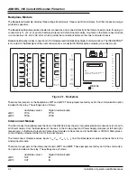
The front (operator) panel provides a convenient means of checking or changing settings, and for checking relay unit
operations after a fault. Information on fault location, trip types, phase, operating units, and breakers which tripped
become available by using the keys to step thru the information. Targets (fault data) from the last two faults are retained,
even if the relay is deenergized. The operator is notified that targets are available by red flashing LEDs on the front
panel; in addition, alarm output-relay contacts are provided for the external annunciators.
The operator can identify nonfault voltage, current and phase angle on the front panel display. Settings can be checked
easily, however, any change to the settings requires the use of the keys. When relay is in the normal operating mode, it
is good practice to set the LED on the Volts/Amps/Angle mode.
Settings Mode
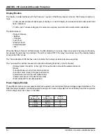
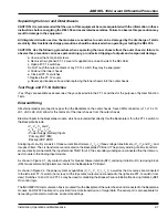
In order to determine the REL 356 settings that have been entered into the system, continually depress the “DISPLAY
SELECT” key until the “SETTINGS” LED is illuminated. Then depress the “FUNCTION RAISE” or “FUNCTION LOWER”
key, in order to scroll thru the REL 356 SETTINGS functions. For each settings function displayed, depress the “VALUE
RAISE” or “VALUE LOWER” key in order to scroll thru the REL 356 values available for the particular function. (Each
value that appears, as each different function appears in the function field, is considered to be the “current value” used
for that particular function.)
In order to change the “current value” of a particular settings function, “RAISE” or “LOWER” the FUNCTION field until the
desired function appears (e.g., “RP”). Then “RAISE” or “LOWER” the values in the VALUE field until the desired value
appears. If the “ENTER” key (recessed for security purposes) is depressed, the value which appears in the VALUE field
will replace the “current value” in memory; but only if the “VALUE ACCEPTED” LED flashes once to indicate that the
value has been successfully entered into the system.
For reasons of security, a plastic screw is used to cover the ENTER key. A wire can be used to lock the plastic screw
and to prevent any unauthorized personnel from changing the settings.
Metering (Volts/Amps/Angle) Mode
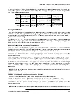
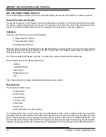
When the Volts/Amps/Angle LED is selected by the “Display Select” key, the phase A, B, C voltages, currents and
phase angles are available for on-line display during normal operation. All measured values can be shown by scrolling
the “Raise” or “Lower” key in the FUNCTION field. The values on the display are dependent on the settings of RP (read
primary); RP= YES for the primary side values and RP = NO for the secondary values. Conditions such as channel
receive, channel transmit and loss-of-potential can also be monitored.
NOTE: All displayed Phase Angles use V
A
as reference.
Target (LAST and PREVIOUS FAULT) Mode
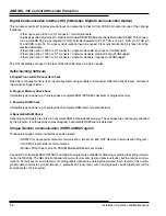
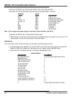
The last two Fault records are assessable at the Front panel. The “LAST FAULT” information is of the most recent fault,
the “PREVIOUS FAULT” information is of the fault prior to the “LAST FAULT”. These displays contain the target
information along with the “Frozen” data at the time of trip. The “LAST FAULT” register shows one or two records stored
by flashing the LED once or twice per second, respectively.
and “LAST FAULT” will not be reset from the front panel key switch, but will be reset from External Reset (TB5-7 and
TB5-8) and the remote reset through the Communication Interface.
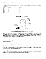
The “Function Raise” and “Function Lower” keys are used to scroll thru the information for the selected display mode.
The “Value Raise” and “Value Lower” keys are used to scroll thru the different values available for each of the five
functions. The “Enter” key is used to enter (in memory) new value for settings.
Summary of Contents for REL 356
Page 23: ...ABB REL 356 Current Differential Protection 1 10 Product Overview and Specifications ...
Page 83: ...ABB REL 356 Current Differential Protection 3 36 Settings and Application ...
Page 127: ...ABB REL 356 Current Differential Protection 5 28 Testing ...
Page 186: ...LINE SECTIONALIZING USING A PLC AND ABB PROTECTIVE RELAY Page 49 of 53 ...
Page 187: ...LINE SECTIONALIZING USING A PLC AND ABB PROTECTIVE RELAY Page 50 of 53 ...
Page 188: ...LINE SECTIONALIZING USING A PLC AND ABB PROTECTIVE RELAY Page 51 of 53 ...
Page 189: ...LINE SECTIONALIZING USING A PLC AND ABB PROTECTIVE RELAY Page 52 of 53 ...


