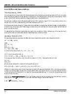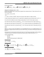
ABB REL 356 Current Differential Protection
2-19
Installation, Operation and Maintenance
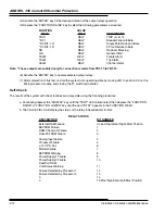
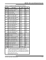
DSBL
–
Transmission of differential protection disable tothe remote relay
OPBR –
Transmission of open breaker information to the distant unit
DCER –
Failure to communicate with the local DCE (Modem or CODEC)
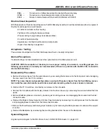
Routine Visual Inspection
With the exception of Routine Visual Inspection, the REL 356 relay assembly should be maintenance-free. A program of
Routine Visual Inspection should include:
• Condition of cabinet or other housing
• Tightness of mounting hardware and fuses
• Proper seating of plug-in relays and subassemblies
• Condition of external wiring
• Appearance of printed circuit boards and components
• Signs of overheating in equipment
Acceptance Testing
The customer should perform the REL 356 Acceptance Tests on receipt of shipment.
Normal Precautions
Troubleshooting is not recommended due to the sophistication of the Microprocessor unit.
CAUTION
CAUTION: With the exception of checking to insure proper mating of connectors, or setting jumpers, the
following procedures are normally not recommended. (If there is a problem with the REL 356, it should be
returned to the factory.)
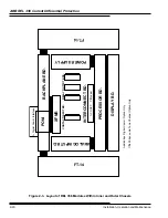
Disassembly Procedures
a. Remove the inner chassis from the outer chassis, by unscrewing the lockscrew (on the front panel), and unsnapping
the two covers from the FT-14 switches.
NOTE: The inner-chassis (sub-assembly) slides in and out of the outer chassis from the front. Mating connec-
tors inside the case eliminate the need to disconnect external wiring when the inner chassis is removed.
b. Remove the FT-14 switches, mounted by two screws on the side walls.
c. Remove the front panel (with the Display module) from the inner chassis, by unscrewing four screws behind the front
panel.
d. Remove the Microprocessor module, by loosening six mounting screws, and unplugging the module from the Inter
connect module.
e. Remove the Modem, Relay Output and Contact Input modules by unscrewing 2 mounting screws from the brackets
and unplugging these modules from the Interconnect module.
f. Remove the Power Supply and Analog Input modules, by first removing the Microprocessor module and the support
cross bar.
g. Remove the Backplate, by unscrewing the mounting hardware from the rear of the Backplate.
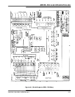
System Diagrams
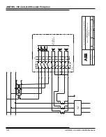
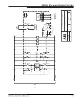
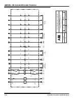
A typical system diagram for the REL 356 is show in DWG 2097D40 sheets 1-3, page 2-22.
Summary of Contents for REL 356
Page 23: ...ABB REL 356 Current Differential Protection 1 10 Product Overview and Specifications ...
Page 83: ...ABB REL 356 Current Differential Protection 3 36 Settings and Application ...
Page 127: ...ABB REL 356 Current Differential Protection 5 28 Testing ...
Page 186: ...LINE SECTIONALIZING USING A PLC AND ABB PROTECTIVE RELAY Page 49 of 53 ...
Page 187: ...LINE SECTIONALIZING USING A PLC AND ABB PROTECTIVE RELAY Page 50 of 53 ...
Page 188: ...LINE SECTIONALIZING USING A PLC AND ABB PROTECTIVE RELAY Page 51 of 53 ...
Page 189: ...LINE SECTIONALIZING USING A PLC AND ABB PROTECTIVE RELAY Page 52 of 53 ...

