ABB REL 356 Current Differential Protection
3-5
Settings and Application
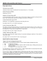
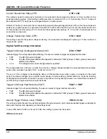
Trigger for Storing Fault Records (FDAT)
Indicates trigger for fault record gathering. The user can select to trigger fault records when:
·
TRIP
The REL 356 system tripped
·
ITRG
The REL 356 system detected the operation of either the TRGP (phase) or TRGG (ground) overcurrent
elements (see below)
Ground Trigger Pick Up Level (TRGG)
This setting controls the level of current magnitude on the ground current, which when exceeded triggers oscillographic
data and/or fault records, depending on the settings above.
In case OSC and/or FDAT are not set to ITRG, this setting is ignored by the system.
Phase Trigger Pick Up Level (TRGP)
This setting controls the level of current magnitude on the phase currents, which when exceeded triggers oscillographic
data and/or fault records, depending on the settings above.
In case OSC and/or FDAT are not set to ITRG, this setting is ignored by the system.
Protection System Settings
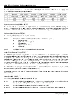
Change Detector (CD)
The change detector CD is used for supervision of the differential trip function. All relay current inputs (I
A
,
I
B
, I
C
and I
G
)
and voltage inputs (V
A
, V
B
, and V
C
) are sampled and converted to numbers 12 times per cycle. The present samples are
compared to the corresponding samples taken one cycle earlier.
The change detector is asserted if the absolute difference of present and old sample exceeds 12.5% of the old sample
and the difference is larger than 0.1 p.u. for current and 7 V for voltage.
The CD can be generated either by using the current change detectors (
D
I) or the current and voltage change detectors
(
D
V
D
I). The
D
V
D
I setting is recommended when the system has voltage inputs and the relay will be used in a weak feed
application where the change in current might not be sufficient to trigger the change detector.
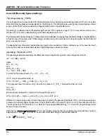
Dedicated Direct Transfer Trip (DDTT)
When the extended output board with additional trip contacts is not included, no DDTT setting is available and a received
transfer trip signal will always result in closure of the two main trip contacts, TRIP–1 and TRIP–2.
When the extended output board is included, the following setting options are available:
DDTT = 0
All trips, trips from the local relay as well as received direct transfer trip, result in closing of all six trip and all six BFI
contacts; TRIP-1, TRIP-2, TRIP-3, TRIP-4, TRIP-5, TRIP-6, BFI-1, BFI-2, BFI-3, BFI-4, BFI-5 and BFI-6.
DDTT = 2
Trips from the local relay will result in closing of trip and BFI contacts TRIP–1, TRIP-2, TRIP-3, TRIP-4, BFI-1, BFI-2,
BFI-3 and BFI-4. Received transfer trip will close contacts TRIP-5, TRIP-6, BFI-5 and BFI-6.
DDTT = 4
Trips from the local relay will result in closing of trip and BFI contacts TRIP–1, TRIP-2, BFI-1 and BFI-2. Received
transfer trip will close contacts TRIP-3, TRIP-4, TRIP-5, TRIP-6, BFI-3, BFI-4, BFI-5 and BFI-6.
Summary of Contents for REL 356
Page 23: ...ABB REL 356 Current Differential Protection 1 10 Product Overview and Specifications ...
Page 83: ...ABB REL 356 Current Differential Protection 3 36 Settings and Application ...
Page 127: ...ABB REL 356 Current Differential Protection 5 28 Testing ...
Page 186: ...LINE SECTIONALIZING USING A PLC AND ABB PROTECTIVE RELAY Page 49 of 53 ...
Page 187: ...LINE SECTIONALIZING USING A PLC AND ABB PROTECTIVE RELAY Page 50 of 53 ...
Page 188: ...LINE SECTIONALIZING USING A PLC AND ABB PROTECTIVE RELAY Page 51 of 53 ...
Page 189: ...LINE SECTIONALIZING USING A PLC AND ABB PROTECTIVE RELAY Page 52 of 53 ...

