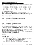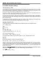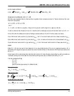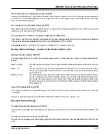
ABB REL 356 Current Differential Protection
3-20
Settings and Application
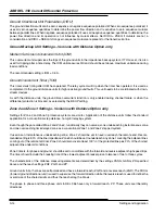
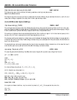
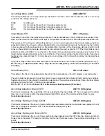
Current Transformer Ratio (CTR)
CTR = 240
This setting is used for load current monitoring, if it is selected to be displayed in primary kA. It has no effect on the
protective relaying system. Note that the metering accuracy for currents is 5% or 0.1 A secondary. The 0.1 A step will
be multiplied with CTR, why the error will appear larger on a primary basis.
Different CT ratios can be used in the two line ends by adjusting the operating threshold, OTH, so that the same level is
achieved on a primary basis. For example, if one end has a ratio of 240 and OTH is set to
0.5 A, the other end with ratio
120 should have an OTH setting of 1.0 A. Note that the sequence filter settings, C1, C2 and C0, should always be the
same at the two line ends.
Voltage Transformer Ratio (VTR)
VTR = 1200
This setting is used for the system voltage monitoring, if it is selected to be displayed in primary kV. It has no effect on
the protective system.
Digital Fault Recording Information
Trigger for Storing Oscillographic Data (OSC)
OSC = TRIP
Indicates trigger for oscillographic data gathering. The user can select to trigger oscillographic data when:
·
TRIP
The REL 356 system tripped
·
ITRG
The REL 356 system detected the operation of either the TRGP (phase) or TRGG (ground) overcurrent
elements (see below)
·
D
V
D
I
The voltage and/or current change detectors operated
The change detectors (CD) pick up when the current or voltage change between the corresponding data samples,
spaced one cycle apart, exceeds 12.5%, minimum 0.5 A or 7 V.
The use of CD as a trigger of oscillographic data is of little practical value when a relay is connected to the power
system. Numerous changes due to sudden load changes, remote switching, distant faults, etc. make the resulting
oscillographic records difficult to relate to events of importance. During testing however, I can sometimes be useful to
use this setting to capture records for external faults.
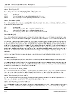
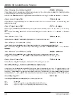
Trigger for Storing Fault Records (FDAT)
FDAT = TRIP
Indicates trigger for fault record gathering. The user can select to trigger fault records when:
·
TRIP
The REL 356 system tripped
·
ITRG
The REL 356 system detected the operation of either the TRGP (phase) or TRGG (ground) overcurrent
elements (see below)
Ground Trigger Pick Up Level (TRGG)
TRGG = 0.5 A
This setting controls the level of current magnitude on the ground current, which when exceeded triggers oscillographic
data and/or fault records, depending on the settings above.
In case OSC and/or FDAT are not set to ITRG, this setting is ignored by the system.
ITRG level not used
Summary of Contents for REL 356
Page 23: ...ABB REL 356 Current Differential Protection 1 10 Product Overview and Specifications ...
Page 83: ...ABB REL 356 Current Differential Protection 3 36 Settings and Application ...
Page 127: ...ABB REL 356 Current Differential Protection 5 28 Testing ...
Page 186: ...LINE SECTIONALIZING USING A PLC AND ABB PROTECTIVE RELAY Page 49 of 53 ...
Page 187: ...LINE SECTIONALIZING USING A PLC AND ABB PROTECTIVE RELAY Page 50 of 53 ...
Page 188: ...LINE SECTIONALIZING USING A PLC AND ABB PROTECTIVE RELAY Page 51 of 53 ...
Page 189: ...LINE SECTIONALIZING USING A PLC AND ABB PROTECTIVE RELAY Page 52 of 53 ...

