176
Supervision of AC input quantities (DA)
Chapter 11
Monitoring
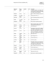
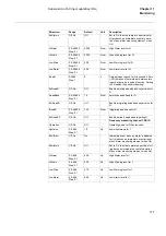
Active power measuring channel P:
DA13-
Operation
Off, On
Off
-
Operating mode for DAnn function
Hysteres
0.0-9999.9
Step. 0.1
5.0
MW
Alarm hysteresis for P
EnAlRem
Off, On
On
-
Immediate event when an alarm is disabled
for P (produces an immediate event at reset
of any alarm monitoring element, when On)
EnAlarms
Off, On
Off
-
Set to 'On' to activate alarm supervision for P
(produces an immediate event at operation
of any alarm monitoring element, when On)
HiAlarm
0.0-9999.9
Step: 0.1
300.0
MW
High Alarm level for P
HiWarn
0.0-9999.9
Step: 0.1
200.0
MW
High Warning level for P
LowWarn
0.0-9999.9
Step: 0.1
80.0
MW
Low Warning level for P
LowAlarm
0.0-9999.9
Step: 0.1
50.0
MW
Low Alarm level for P
RepInt
0-3600
Step: 1
0
s
Time between reports for P in seconds. Zero
= Off (duration of time interval between two
reports at periodic reporting function. Setting
to 0 disables the periodic reporting)
EnDeadB
Off, On
Off
-
Enable amplitude dead band supervision for
P
DeadBand
0.0-9999.9
Step: 0.1
1.0
MW
Amplitude dead band for P
EnIDeadB
Off, On
Off
-
Enable integrating dead band supervision for
P
IDeadB
0.0-9999.9
Step: 0.1
10.0
MW
Integrating dead band for P
EnDeadBP
Off, On
Off
-
Enable periodic dead band reporting P
Reactive power measuring channel Q:
DA14-
Operation
Off, On
Off
-
Operating mode for DAnn function
Hysteres
0.0-9999.9
Step: 0.1
5.0
Mvar
Alarm hysteresis for Q
EnAlRem
Off, On
On
-
Immediate event when an alarm is disabled
for Q (produces an immediate event at reset
of any alarm monitoring element, when On)
Parameter
Range
Default
Unit
Description
Summary of Contents for REL 501-C1 2.5
Page 1: ...Technical reference manual Line distance protection terminal REL 501 C1 2 5 ...
Page 2: ......
Page 26: ...14 Introduction to the technical reference manual Chapter 1 Introduction ...
Page 42: ...30 Technical data Chapter 2 General ...
Page 66: ...54 Blocking of signals during test BST Chapter 3 Common functions ...
Page 142: ...130 Time delayed overvoltage protection TOV Chapter 6 Voltage ...
Page 162: ...150 Autorecloser AR Chapter 9 Control ...
Page 174: ...162 Event function EV Chapter 10 Logic ...
Page 210: ...198 Serial communication Chapter 12 Data communication ...
Page 226: ...214 Serial communication modules SCM Chapter 13 Hardware modules ...
Page 230: ...218 Terminal diagrams Chapter 14 Diagrams Figure 87 REL 501 C1 with DC switch ...
Page 234: ...222 Terminal diagrams Chapter 14 Diagrams ...
Page 237: ......


