200
Modules
Chapter 13
Hardware modules
1
Modules
Table 209: Basic, always included, modules
Table 210: Application specific modules
Module
Description
Backplane module (BPM)
Carries all internal signals between modules in a termi-
nal. The size of the module depends on the size of the
case.
Power supply module (PSM)
Including a regulated DC/DC converter that supplies
auxiliary voltage to all static circuits.
•
For case size 1/2x19” and 3/4x19” a version with
four binary inputs and four binary outputs used.
An internal fail alarm output is also available.
Main processing module (MPM)
Module for overall application control. All information is
processed or passed through this module, such as
configuration, settings and communication. Carries up
to 12 digital signal processors, performing all measur-
ing functions.
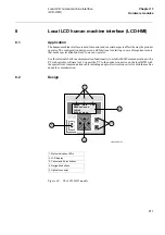
Human machine interface (LCD-HMI)
The module consist of LED:s, a LCD, push buttons
and an optical connector for a front connected PC
Signal processing module (SPM)
Module for protection algorithm processing. Carries up
to 12 digital signal processors, performing all measur-
ing functions.
Module
Description
Binary input module (BIM)
Module with 16 optically isolated binary inputs
Binary output module (BOM)
Module with 24 single outputs or 12 double-pole com-
mand outputs including supervision function
Transformer input module (TRM)
Used for galvanic separation of voltage and/or current
process signals and the internal circuitry.
A/D conversion module (ADM)
Used for analog to digital conversion of analog pro-
cess signals galvanically separated by the TRM.
Serial communication module (SCM)
Used for SPA/LON/IEC communication
Summary of Contents for REL 501-C1 2.5
Page 1: ...Technical reference manual Line distance protection terminal REL 501 C1 2 5 ...
Page 2: ......
Page 26: ...14 Introduction to the technical reference manual Chapter 1 Introduction ...
Page 42: ...30 Technical data Chapter 2 General ...
Page 66: ...54 Blocking of signals during test BST Chapter 3 Common functions ...
Page 142: ...130 Time delayed overvoltage protection TOV Chapter 6 Voltage ...
Page 162: ...150 Autorecloser AR Chapter 9 Control ...
Page 174: ...162 Event function EV Chapter 10 Logic ...
Page 210: ...198 Serial communication Chapter 12 Data communication ...
Page 226: ...214 Serial communication modules SCM Chapter 13 Hardware modules ...
Page 230: ...218 Terminal diagrams Chapter 14 Diagrams Figure 87 REL 501 C1 with DC switch ...
Page 234: ...222 Terminal diagrams Chapter 14 Diagrams ...
Page 237: ......


