41
Self supervision with internal event recorder
(INT)
Chapter 3
Common functions
5.3
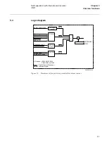
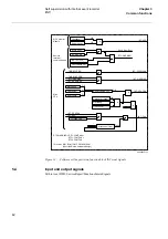
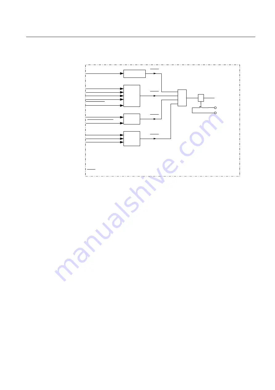
Logic diagram
Figure 13:
Hardware self-supervision, potential-free alarm contact.
Power supply fault
W atchdog
TX overflow
Master resp.
Supply fault
ReBoot I/O
Checksum fault
Supply fault
Parameter check
Power supply
module
I/O nodes
A/D conv.
module
Main CPU
&
Fault
Fault
Fault
Fault
INTERNAL
FAIL
I/O nodes = BIM, BOM, IOM
PSM, MIM or DCM
DSP = Digital Signal Processor
xxxx = Inverted signal
99000034.vsd
Summary of Contents for REL 501-C1 2.5
Page 1: ...Technical reference manual Line distance protection terminal REL 501 C1 2 5 ...
Page 2: ......
Page 26: ...14 Introduction to the technical reference manual Chapter 1 Introduction ...
Page 42: ...30 Technical data Chapter 2 General ...
Page 66: ...54 Blocking of signals during test BST Chapter 3 Common functions ...
Page 142: ...130 Time delayed overvoltage protection TOV Chapter 6 Voltage ...
Page 162: ...150 Autorecloser AR Chapter 9 Control ...
Page 174: ...162 Event function EV Chapter 10 Logic ...
Page 210: ...198 Serial communication Chapter 12 Data communication ...
Page 226: ...214 Serial communication modules SCM Chapter 13 Hardware modules ...
Page 230: ...218 Terminal diagrams Chapter 14 Diagrams Figure 87 REL 501 C1 with DC switch ...
Page 234: ...222 Terminal diagrams Chapter 14 Diagrams ...
Page 237: ......


