91
Power swing detection (PSD)
Chapter 4
Line distance
5.7
Technical data
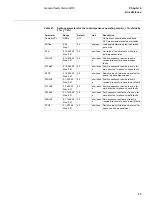
Table 102: PSD - Power swing detection
KR
120 - 200
Step: 1
125
%
Reach multiplication factor for the outer
resistive boundary
tP1
0.000 -
60.000
Step: 0.001
0.045
s
Timer for detection of initial power swings
tP2
0.000 -
60.000
Step: 0.001
0.015
s
Timer for detection of subsequent power
swings
tW
0.000 -
60.000
Step: 0.001
0.250
s
Waiting timer for activation of tP2 timer
tH
0.000 -
60.000
Step: 0.001
0.500
s
Timer for holding PSD output
tEF
0.000 -
60.000
Step: 0.001
3.000
s
Timer for overcoming single-pole reclos-
ing dead time
tR1
0.000 -
60.000
Step: 0.001
0.300
s
Timer giving delay to blocking of output
by the residual current
tR2
0.000 -
60.000
Step: 0.001
2.000
s
Timer giving delay to blocking of output at
very slow swings
Parameter
Range
Default
Unit
Description
Parameter
Setting range
Accuracy
Impedance setting range at I
r
=1A
(divide values by 5 for I
r
= 5A)
Reactive reach, XIN
0.10-400.00 ohm/phase
in steps of 0.01
ohm/phase
Resistive reach, RIN 0.10-400.00 ohm/phase
in steps
of 0.01ohm/phase
Reach multiplication factor, KX
120-200% of XIN in steps
of 1%
Reach multiplication factor, KR
120-200% of RIN in steps
of 1%
Initial PSD timer, tP1
0.000-60.000 s in steps of
1 ms
+/- 0.5 % +/- 10 ms
Fast PSD timer, tP2
0.000-60.000 s in steps of
1 ms
+/- 0.5 % +/- 10 ms
Summary of Contents for REL 501-C1 2.5
Page 1: ...Technical reference manual Line distance protection terminal REL 501 C1 2 5 ...
Page 2: ......
Page 26: ...14 Introduction to the technical reference manual Chapter 1 Introduction ...
Page 42: ...30 Technical data Chapter 2 General ...
Page 66: ...54 Blocking of signals during test BST Chapter 3 Common functions ...
Page 142: ...130 Time delayed overvoltage protection TOV Chapter 6 Voltage ...
Page 162: ...150 Autorecloser AR Chapter 9 Control ...
Page 174: ...162 Event function EV Chapter 10 Logic ...
Page 210: ...198 Serial communication Chapter 12 Data communication ...
Page 226: ...214 Serial communication modules SCM Chapter 13 Hardware modules ...
Page 230: ...218 Terminal diagrams Chapter 14 Diagrams Figure 87 REL 501 C1 with DC switch ...
Page 234: ...222 Terminal diagrams Chapter 14 Diagrams ...
Page 237: ......


