98
Current reversal and weak-end infeed logic
(ZCAL)
Chapter 4
Line distance
7
Current reversal and weak-end infeed logic (ZCAL)
7.1
Application
In interconnected systems, for parallel line applications, the direction of flow of the fault current
on the healthy line can change when the circuit breakers on the faulty line open to clear the fault.
This can lead to unwanted operation of the protection on the healthy line when permissive over-
reach schemes are used. The main purpose of the ZCAL current reversal logic is to prevent such
unwanted operations for this phenomenon.
If the infeed of fault current at the local end for faults on the protected line is too low to operate
the measuring elements, no trip output will be issued at the local end and no teleprotection signal
will be sent to the remote end. This can lead to time delayed tripping at the remote strong infeed
end. The main purpose of the ZCAL weak end infeed logic is to enhance the operation of per-
missive communication schemes and to avoid sequential tripping when, for a fault on the line,
the initial infeed of fault current from one end is too weak to operate the measuring elements.
7.2
Functionality
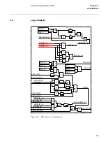
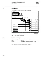
The ZCAL function block provides the current reversal and weak end infeed logic functions that
supplement the standard scheme communication logic, or the phase segregated scheme commu-
nication logic.
On detection of a current reversal, the current reversal logic provides an output to block the send-
ing of the teleprotection signal to the remote end, and to block the permissive tripping at the local
end. This blocking condition is maintained long enough to ensure that no unwanted operation
will occur as a result of the current reversal.
On verification of a weak end infeed condition, the weak end infeed logic provides an output for
sending the received teleprotection signal back to the remote sending end, and other output(s)
for tripping. For terminals equipped for single-, two-, and three-pole tripping, outputs for the
faulted phase(s) are provided. Undervoltage detectors are used to select the faulted phase (s).
Note!
Current reversal and week end infeed logic (ZCAL) and General fault criteria (GFC) including
phase preference logic cannot be ordered together.
Summary of Contents for REL 501-C1 2.5
Page 1: ...Technical reference manual Line distance protection terminal REL 501 C1 2 5 ...
Page 2: ......
Page 26: ...14 Introduction to the technical reference manual Chapter 1 Introduction ...
Page 42: ...30 Technical data Chapter 2 General ...
Page 66: ...54 Blocking of signals during test BST Chapter 3 Common functions ...
Page 142: ...130 Time delayed overvoltage protection TOV Chapter 6 Voltage ...
Page 162: ...150 Autorecloser AR Chapter 9 Control ...
Page 174: ...162 Event function EV Chapter 10 Logic ...
Page 210: ...198 Serial communication Chapter 12 Data communication ...
Page 226: ...214 Serial communication modules SCM Chapter 13 Hardware modules ...
Page 230: ...218 Terminal diagrams Chapter 14 Diagrams Figure 87 REL 501 C1 with DC switch ...
Page 234: ...222 Terminal diagrams Chapter 14 Diagrams ...
Page 237: ......


