152
Tripping logic (TR)
Chapter 10
Logic
1
Tripping logic (TR)
1.1
Application
The main purpose of the TR trip logic function is to serve as a single node through which all
tripping for the entire terminal is routed.
To meet the different single, double, 1 and 1/2 or other multiple circuit breaker arrangements,
one or more identical TR function blocks may be provided within a single terminal. The actual
number of these TR function blocks that may be included within any given terminal depends on
the type of terminal. Therefore, the specific circuit breaker arrangements that can be catered for,
or the number of bays of a specific arrangement that can be catered for, depends on the type of
terminal.
1.2
Functionality
The minimum duration of a trip output signal from the TR function is settable.
The TR function has a single input through which all trip output signals from the protection func-
tions within the terminal, or from external protection functions via one or more of the terminal’s
binary inputs, are routed. It has a single trip output for connection to one or more of the termi-
nal’s binary outputs, as well as to other functions within the terminal requiring this signal.
1.3
Input and output signals
Note
: Some signals may not be present depending on the ordered option.
Table 153: Input signals for the TR (TRnn-) function block
Note
: Some signals may not be present depending on the ordered option.
Path in local HMI: ServiceReport/Functions/TRn/FuncOutputs
Table 154: Output signals for the TR (TRnn-) function block
1.4
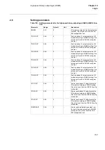
Setting parameters
Path in local HMI: Settings/Functions/Groupn/TRn
Signal
Description
BLOCK
Block trip logic
TRIN
Trip all phases
Signal
Description
TRIP
General trip output signal
Summary of Contents for REL 501-C1 2.5
Page 1: ...Technical reference manual Line distance protection terminal REL 501 C1 2 5 ...
Page 2: ......
Page 26: ...14 Introduction to the technical reference manual Chapter 1 Introduction ...
Page 42: ...30 Technical data Chapter 2 General ...
Page 66: ...54 Blocking of signals during test BST Chapter 3 Common functions ...
Page 142: ...130 Time delayed overvoltage protection TOV Chapter 6 Voltage ...
Page 162: ...150 Autorecloser AR Chapter 9 Control ...
Page 174: ...162 Event function EV Chapter 10 Logic ...
Page 210: ...198 Serial communication Chapter 12 Data communication ...
Page 226: ...214 Serial communication modules SCM Chapter 13 Hardware modules ...
Page 230: ...218 Terminal diagrams Chapter 14 Diagrams Figure 87 REL 501 C1 with DC switch ...
Page 234: ...222 Terminal diagrams Chapter 14 Diagrams ...
Page 237: ......


