160
Event function (EV)
Chapter 10
Logic
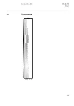
3.4
Input and output signals
Table 160: Input signals for the EVENT (EVnn-) function block
3.5
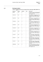
Setting parameters
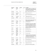
Table 161: Setting parameters for the EVENT (EVnn-) function
Signal
Description
INPUTy
Event input y, y=1-16
NAMEy
User name of signal connected to input y, y=01-16. String length up to
19 characters.
T_SUPR01
Suppression time for event inputs 1and 2
T_SUPR03
Suppression time for event inputs 3 and 4
T_SUPR05
Suppression time for event inputs 5 and 6
T_SUPR07
Suppression time for event inputs 7 and 8
T_SUPR09
Suppression time for event inputs 9 and 10
T_SUPR11
Suppression time for event inputs 11 and 12
T_SUPR13
Suppression time for event inputs 13 and 14
T_SUPR15
Suppression time for event inputs 15 and 16
PrColnn
Protocol for event block nn (nn=01-06). 0: Not used, 1: SPA, 2: LON,
3: SPA+LON, 4: IEC, 5: IEC+SPA, 6: IEC+LON, 7: IEC+LON+SPA.
Protocol for event block nn (nn=07-44). 0: Not used, 1: SPA, 2: LON,
3: SPA+LON
INTERVAL
Time setting for cyclic sending of data
BOUND
Input signals connected to other terminals on the network, 0: not con-
nected, 1: connected
FuncTEVnn
Function type for event block nn (nn=01-06), used for IEC protocol
communication. Only present in blocks EV01-EV06.
InfoNoy
Information number for event input y, y=01-16. Used for IEC protocol
communication. Only present in blocks EV01-EV06.
Parameter
Range
Default
Unit
Description
T_SUPR01
0.000-60.000
Step: 0.001
0.000
s
Suppression time for event input 1 and 3.
Can only be set using the CAP 540 configu-
ration tool.
T_SUPR03
0.000-60.000
Step: 0.001
0.000
s
Suppression time for event input 3 and 4.
Can only be set using the CAP 540 configu-
ration tool.
T_SUPR05
0.000-60.000
Step: 0.001
0.000
s
Suppression time for event input 5 and 6.
Can only be set using the CAP 540 configu-
ration tool.
T_SUPR07
0.000-60.000
Step: 0.001
0.000
s
Suppression time for event input 7 and 8.
Can only be set using the CAP 540 configu-
ration tool.
T_SUPR09
0.000-60.000
Step: 0.001
0.000
s
Suppression time for event input 9 and 10.
Can only be set using the CAP 540 configu-
ration tool.
Summary of Contents for REL 501-C1 2.5
Page 1: ...Technical reference manual Line distance protection terminal REL 501 C1 2 5 ...
Page 2: ......
Page 26: ...14 Introduction to the technical reference manual Chapter 1 Introduction ...
Page 42: ...30 Technical data Chapter 2 General ...
Page 66: ...54 Blocking of signals during test BST Chapter 3 Common functions ...
Page 142: ...130 Time delayed overvoltage protection TOV Chapter 6 Voltage ...
Page 162: ...150 Autorecloser AR Chapter 9 Control ...
Page 174: ...162 Event function EV Chapter 10 Logic ...
Page 210: ...198 Serial communication Chapter 12 Data communication ...
Page 226: ...214 Serial communication modules SCM Chapter 13 Hardware modules ...
Page 230: ...218 Terminal diagrams Chapter 14 Diagrams Figure 87 REL 501 C1 with DC switch ...
Page 234: ...222 Terminal diagrams Chapter 14 Diagrams ...
Page 237: ......


