69
Distance protection (ZM)
Chapter 4
Line distance
1.14
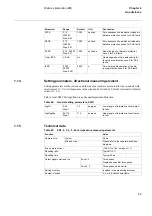
Setting parameters, directional measuring element
Setting parameters for the resistive and the reactive reach are presented for the terminals with
rated current Ir = 1A. All impedance values should be divided by 5 for the terminals with rated
current Ir = 5A.
Path in local HMI: Settings/Functions/Groupn/Impedance/Direction
Table 84:
General setting parameters, ZDIR
1.15
Technical data
Table 85:
ZM1, 2, 3, 4, 5 - Zone impedance measuring elements
X0PE
0.10 -
1200.00
Step: 0.01
10.00
ohm/ph
Zero sequence line reactance included in
distance protection zone 5 for Ph-E faults
R0PE
0.10 -
1200.00
Step: 0.01
10.00
ohm/ph
Zero sequence line resistance included in
distance protection zone 5 for Ph-E faults
RFPE
0.10 - 400.00
Step: 0.01
10.00
ohm/loop
Resistive reach of distance protection
zone 5 for Ph-E faults
Timer t5PE
Off, On
On
-
Operating mode of time delayed trip for
the distance protection zone 5 for Ph-E
faults
t5PE
0.000 -
60.000
Step: 0.001
0.000
s
Time delayed trip operation of the dis-
tance protection zone 5 for Ph-E faults
Parameter
Range
Default
Unit
Description
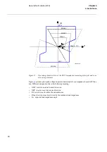
ArgDir
5-45
Step:1
15
degrees
Lower angle of forward direction charac-
teristic
ArgNegRes
90-175
Step:1
115
degrees
Upper angle of forward direction Charac-
teristic
Function
Value
Operate time
Typical
28 ms
Min and max
Please refer to the separate isochrone
diagrams
Min. operate current
(10-30) % of I1b in steps of 1 %
Resetting ratio
Typical 110 %
Resetting time
Typical 40 ms
Output signals start and trip
Zone 1-3
Three phase
Single phase and/or three phase
Zone 4, 5
Three phase start and trip
Setting accuracy
Included in the measuring accuracy
Number of zones
3, 4 or 5, direction selectable
Summary of Contents for REL 501-C1 2.5
Page 1: ...Technical reference manual Line distance protection terminal REL 501 C1 2 5 ...
Page 2: ......
Page 26: ...14 Introduction to the technical reference manual Chapter 1 Introduction ...
Page 42: ...30 Technical data Chapter 2 General ...
Page 66: ...54 Blocking of signals during test BST Chapter 3 Common functions ...
Page 142: ...130 Time delayed overvoltage protection TOV Chapter 6 Voltage ...
Page 162: ...150 Autorecloser AR Chapter 9 Control ...
Page 174: ...162 Event function EV Chapter 10 Logic ...
Page 210: ...198 Serial communication Chapter 12 Data communication ...
Page 226: ...214 Serial communication modules SCM Chapter 13 Hardware modules ...
Page 230: ...218 Terminal diagrams Chapter 14 Diagrams Figure 87 REL 501 C1 with DC switch ...
Page 234: ...222 Terminal diagrams Chapter 14 Diagrams ...
Page 237: ......


