77
General fault criteria (GFC)
Chapter 4
Line distance
4
General fault criteria (GFC)
4.1
Application
The GFC general fault criteria function is an independent measuring function. It comprises both
impedance and current-based measurement criteria. These can be used separately or at the same
time. Its main purpose is to serve as an overall fault detection and phase selection element in all
kinds of networks or as an individual underimpedance measuring function. It is not used as a
start condition because the distance protection zones utilize full scheme measurement.
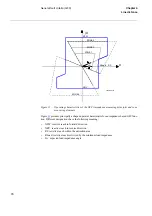
For the impedance measurement, the shape of the operating characteristic can be set to prevent
operation of the impedance measuring elements for low load impedances, yet at the same time
allow coverage of higher fault resistances with remote infeed of fault current. This makes the
GFC function especially suited to cases where the fault resistance to be detected exceeds the
minimum expected load impedance.
The independent measurement of impedance for each fault loop secures reliable phase selection
and correct operation for complex network faults such as simultaneous faults on parallel circuits,
evolving faults, etc. Independent reactive reach settings for phase-to-phase and phase-to-ground
measurement secure high selectivity in networks with different protective relays used for
short-circuit and earth-fault protection.
4.2
Functionality
For the impedance-based phase selection, all six fault loops are measured separately and contin-
uously. The reaches are independently settable in the forward and reverse directions, and for
phase-to-phase and phase-to-ground faults. The resistive reaches are also independently settable
for phase-to-phase and phase-to-ground faults. Preventing impedance element operation due to
low load impedances, but at the same time enabling the GFC function to be as sensitive as pos-
sible to faults with high fault resistances, is achieved by the inclusion of a facility that allows the
resistive reach to be limited within the load impedance area only.
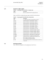
Checks based on the level of residual current determine which loops, i.e. phase-to-ground or
phase-to-phase, are evaluated. Selection of the faulted phase(s) is determined by which of the
selected loops operate. Operation of a loop occurs when the measured impedance within that
loop is within the set boundaries of the characteristic.
For the current-based phase selection, all three phase currents and the residual current are mea-
sured continuously, and compared to set values. Assessment of the type of fault is based on the
relationship of the measured currents to the set thresholds.
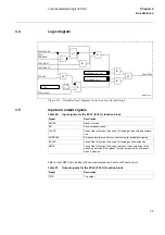
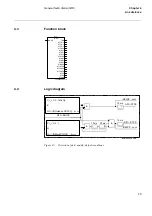
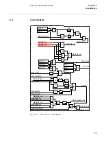
The GFC starting condition (STCND) output will activate the selected loop of the distance pro-
tection measuring zone(s) to which it is connected.
Summary of Contents for REL 501-C1 2.5
Page 1: ...Technical reference manual Line distance protection terminal REL 501 C1 2 5 ...
Page 2: ......
Page 26: ...14 Introduction to the technical reference manual Chapter 1 Introduction ...
Page 42: ...30 Technical data Chapter 2 General ...
Page 66: ...54 Blocking of signals during test BST Chapter 3 Common functions ...
Page 142: ...130 Time delayed overvoltage protection TOV Chapter 6 Voltage ...
Page 162: ...150 Autorecloser AR Chapter 9 Control ...
Page 174: ...162 Event function EV Chapter 10 Logic ...
Page 210: ...198 Serial communication Chapter 12 Data communication ...
Page 226: ...214 Serial communication modules SCM Chapter 13 Hardware modules ...
Page 230: ...218 Terminal diagrams Chapter 14 Diagrams Figure 87 REL 501 C1 with DC switch ...
Page 234: ...222 Terminal diagrams Chapter 14 Diagrams ...
Page 237: ......


