77
Automatic reclosing function (AR)
&KDSWHU
9HULI\LQJVHWWLQJVE\VHFRQGDU\
LQMHFWLRQ
$XWRPDWLFUHFORVLQJIXQFWLRQ$5
The test can be divided into to parts; one to verify the internal logic and one to verify
the co-operation with the protection system. This section deals with the first test.
Prepare the terminal for verification of settings as outlined in section “Preparing for
test” in this chapter.
The test is performed together with protection and trip functions.
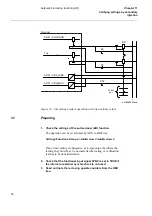
Figure 18 "Simulating
breaker operation with two auxiliary relays." on page 78
illustrates a recommended test-
ing scenario, where the circuit breaker is simulated by an external bistable relay (BR),
for example an RXMVB2 or an RXMVD. The following switches are needed:
•
Switch close (SC)
•
Switch trip (ST)
•
Switch ready (SRY).
SC and ST can be push-buttons with spring return. If no bistable relay is available, re-
place it with two self-reset auxiliary relays and use self-holding connection.
Use a secondary injection relay test set to operate the protection function. It is possible
to use the BR to control the injected analogue quantities so that the fault only appears
when the BR is picked up—simulating a closed breaker position.
To make the arrangement more elaborate, include the simulation of the operation gear
condition, AR01-CBREADY, for the sequences Close-Open (CO) and Open-Close-
Open (OCO).
The AR01-CBREADY condition at the CO sequence type is usually low for a recharg-
ing time of 5-10 s after a closing operation. Then it is high. The example in
figure 18
"Simulating breaker operation with two auxiliary relays." on page 78
shows that it is
simulated with SRY, a manual switch.
Summary of Contents for REL 531
Page 16: ...10 Note signs KDSWHU 6DIHW LQIRUPDWLRQ ...
Page 44: ...38 Checking the binary I O circuits KDSWHU KHFNLQJ WKH H WHUQDO FLUFXLWU ...
Page 52: ...46 Checking the self supervision signals KDSWHU QHUJLVLQJ WKH WHUPLQDO ...
Page 140: ...134 Testing the interaction of the distance protection KDSWHU 7HVWLQJ WKH SURWHFWLRQ V VWHP ...

