22. Technical data
General
IP11376-1 v3
M10993-1 v4
Definitions
Reference value
The specified value of an influencing factor to which are referred the characteristics of the equipment
Nominal range
The range of values of an influencing quantity (factor) within which, under specified conditions, the equipment meets the
specified requirements
Operative range
The range of values of a given energizing quantity for which the equipment, under specified conditions, is able to perform its
intended functions according to the specified requirements
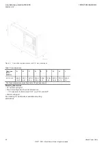
• Maximum 176 binary input channels may be activated
simultaneously with influencing factors within nominal
range.
• The stated operate time for functions include the
operating time for the binary inputs and outputs.
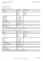
• Maximum 72 outputs may be activated simultaneously
with influencing factors within nominal range. After 6 ms
an additional 24 outputs may be activated. The activation
time for the 96 outputs must not exceed 200 ms. 48
outputs can be activated during 1 s. Continued activation
is possible with respect to current consumption but after 5
minutes the temperature rise will adversely affect the
hardware life. Maximum two relays per BOM/IOM/SOM
should be activated continuously due to power
dissipation. BOM/IOM/SOM should be activated
continuously due to power dissipation.
• Maximum two relays per BOM/IOM/SOM should be
activated continuously due to power dissipation. The
stated operate time for functions include the operating
time for the binary inputs and outputs.
Presumptions for Technical Data
GUID-1E949E38-E04D-4374-A086-912C25E9F93C v3
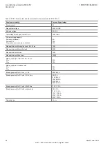
The technical data stated in this document are only valid
under the following circumstances:
1. Main current transformers with 1 A or 2 A secondary
rating are wired to the IED 1 A rated CT inputs.
2. Main current transformer with 5 A secondary rating are
wired to the IED 5 A rated CT inputs.
3. CT and VT ratios in the IED are set in accordance with
the associated main instrument transformers. Note that
for functions which measure an analogue signal which do
not have corresponding primary quantity the 1:1 ratio
shall be set for the used analogue inputs on the IED.
Example of such functions are: HZPDIF, ROTIPHIZ and
STTIPHIZ.
4. Parameter
IBase
used by the tested function is set equal
to the rated CT primary current.
5. Parameter
UBase
used by the tested function is set equal
to the rated primary phase-to-phase voltage.
6. Parameter
SBase
used by the tested function is set equal
to:
– √3 ×
IBase
×
UBase
7. The rated secondary quantities have the following values:
– Rated secondary phase current I
r
is either 1 A or 5 A
depending on selected TRM.
– Rated secondary phase-to-phase voltage U
r
is within
the range from 100 V to 120 V.
– Rated secondary power for three-phase system S
r
= √3
× U
r
× I
r
8. For operate and reset time testing, the default setting
values of the function and BOM module are used if not
explicitly stated otherwise.
All reset times are measured using BOM output contacts
if not explicitly stated otherwise. The operate/reset times
are determined by characteristics of the output module
used.
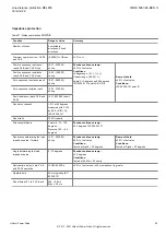
9. During testing, signals with rated frequency have been
injected if not explicitly stated otherwise.
Line distance protection REL650
1MRK 506 384-BEN H
Version 2.2
42
Hitachi Power Grids
© 2017 - 2021 Hitachi Power Grids. All rights reserved


