L1
L2
L3
REB611
16
17
19
18
X100
6
7
8
9
10
11
12
13
15
14
2
1
3
4
5
22
21
23
24
SO2
TCS2
PO4
SO1
TCS1
PO3
PO2
PO1
IRF
+
-
U
aux
20
1) The IED features an automatic short-circuit
mechanism in the CT connector when plug-in
unit is detached
1)
X120
1
2
3
4
5
6
7
8
9
10
11
12
14
Io
IL1
IL2
BI 4
BI 3
BI 2
BI 1
IL3
1/5A
N
1/5A
N
1/5A
N
1/5A
N
13
3~
G
Ru
Rs
GUID-00968A99-E6A2-4649-A50F-28E52CB8F484 V1 EN
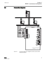
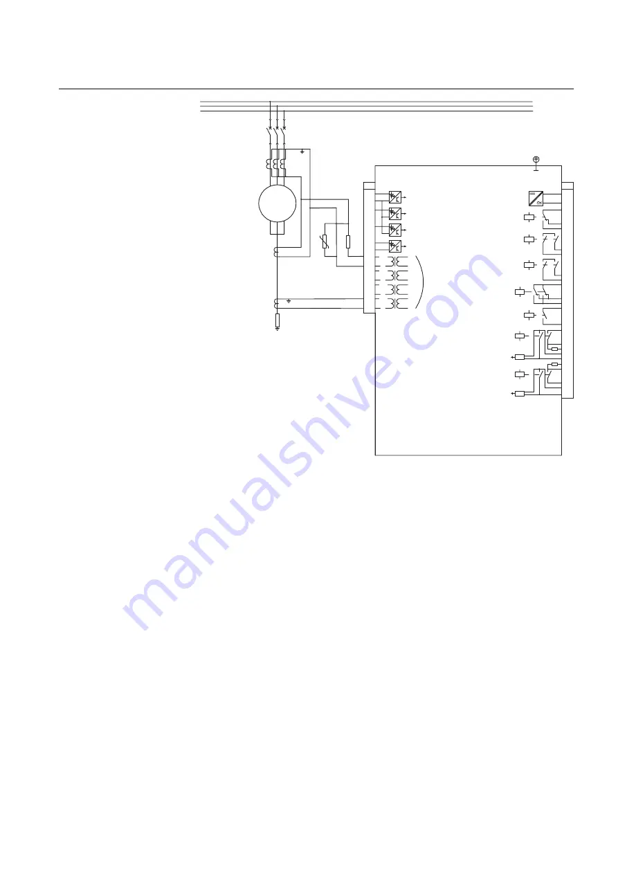
Figure 14:
Connection diagram for configuration A when used as rotating
machine restricted earth-fault protection
3.4
Configuration A
3.4.1
Applications
Configuration A for phase-segregated high-impedance differential protection and
non-directional earth-fault protection is mainly intended for use in high-impedance-
based applications within utility substations and industrial power systems. In addition,
the protection relay can also be used in restricted earth-fault and residual earth-fault
applications for the protection of generators, motors, transformers and reactors.
The protection relay with a standardized configuration is delivered from the factory
with default settings and parameters. The end-user flexibility for incoming, outgoing
and internal signal designation within the protection relay enables this configuration
to be further adapted to different primary circuit layouts and the related functionality
needs by modifying the internal functionality using PCM600.
1MRS757455 E
Section 3
REB611 standardized configuration
REB611
31
Application Manual


