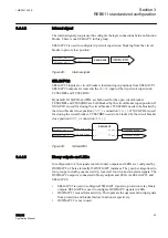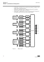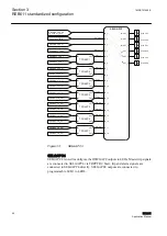
Breaker control CBXCBR and breaker failure protection CCBRBRF are always
associated with one set of phase current inputs. In REB611, the current inputs are
phase differential currents, that is, a vector-sum of all phase feeder currents that flow
in or out of the same bus. The bus differential current is not a feeder phase current and
is normally zero. If a bus fault occurs and any phase differential protection picks up,
all breakers that connect to the bus should be tripped.
As there is only one set of breaker control and breaker failure protection, and multiple
breakers are associated with the bus protection especially when multiple source
feeders are connected to the bus, these functions must be dealt with application-
specifically.
Since the differential current cannot simply reflect any source breaker, the breaker
control and breaker failure protection should be turned off.
3.4.2
Functions
3I>/Io>BF
51BF/51NBF
Io>
51N-1
Io>>
51N-2
REMARKS
Optional
function
No. of
instances
Alternative
function to be
defined when
ordering
OR
3×
Io/Uo
Calculated
value
CONDITION MONITORING
AND SUPERVISION
CONTROL AND INDICATION
1)
MEASUREMENT
- 3I, Io
- Limit value supervision
- Symmetrical components
BUSBAR AND MULTIPURPOSE DIFFERENTIAL PROTECTION RELAY
STANDARD
CONFIGURATION
LOCAL HMI
A
COMMUNICATION
Protocols:
IEC 61850-8-1
Modbus®
Interfaces:
Ethernet: TX (RJ-45), FX (LC)
Serial:
RS-485
Redundant protocols:
HSR
PRP
RSTP
4
-
Analog interface types
1)
Current transformer
Voltage transformer
1)
Conventional transformer inputs
Object
Ctrl
2)
Ind
3)
CB
DC
ES
1
-
-
-
-
-
1)
Check availability of binary inputs/outputs
from technical documentation
2)
Control and indication function for
primary object
3)
Status indication function for
primary object
PROTECTION
3I
ALSO AVAILABLE
- Disturbance and fault recorders
- Event log and recorded data
- Local/Remote push button on LHMI
- Self-supervision
- Time synchronization: IEEE 1588 v2,
SNTP, IRIG-B
- User management
- Web-HMI
TCS
TCM
2×
Io
REB611
MCS 1I
MCS 1I
Master Trip
Lockout relay
94/86
2×
3×
dHi>
87
3I
3×
R
L
ESC
I
O
A
Control
Events
Measurements
Disturbance records
∆3I
GUID-57FB15B3-447A-4D9D-B342-C01EDA83D3F0 V1 EN
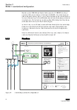
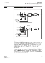
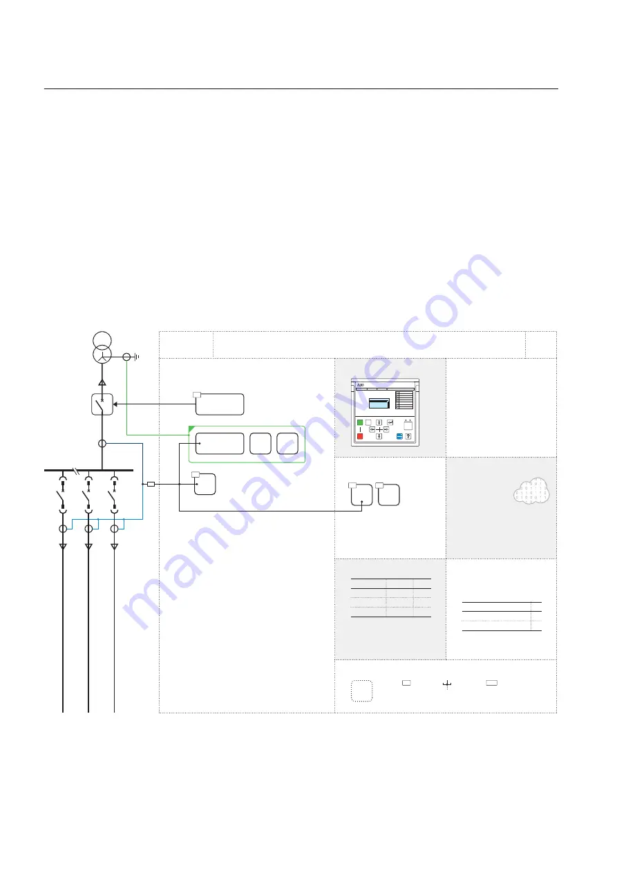
Figure 15:
Functionality overview for configuration A
Section 3
1MRS757455 E
REB611 standardized configuration
32
REB611
Application Manual


