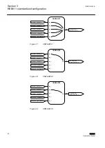
3.4.3.3
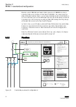
Functional diagrams for control and interlocking
X100 PO3
X100 PO4
MASTER TRIP #1
MASTER TRIP #2
OR
OR
SELGAPC3
OUT_6
IN_2
SELGAPC3
OUT_5
IN_1
TRIP
CL_LKOUT
BLOCK
RST_LKOUT
TRPPTRC1
OPERATE
TRIP
CL_LKOUT
BLOCK
RST_LKOUT
TRPPTRC2
OPERATE
SELGAPC1_RST_LKOUT
CBXCBR1_EXE_OP
SELGAPC1_RST_LKOUT
HIAPDIF1_OPERATE
HIBPDIF1_OPERATE
HICPDIF1_OPERATE
EHLPTOC1_OPERATE
EFHPTOC1_OPETATE
CCBRBRF1_TRRET
HIAPDIF1_OPERATE
HIBPDIF1_OPERATE
HICPDIF1_OPERATE
EHLPTOC1_OPERATE
EFHPTOC1_OPETATE
OSWGAPC2
OR
IN_1
IN_2
IN_3
IN_4
IN_5
IN_6
OUT
OR
OSWGAPC1
OR
IN_1
IN_2
IN_3
IN_4
IN_5
OUT
SELGAPC1_External Trip
Q1
Q2
IN1
IN2
MVGAPC1
OR
GOOSERCV_BIN 2_OUT
GOOSERCV_BIN 3_OUT
SELGAPC1_External Trip
Q1
Q2
IN1
IN2
MVGAPC1
OR
GOOSERCV_BIN 2_OUT
GOOSERCV_BIN 3_OUT
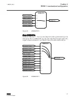
GUID-AFCBCEC5-678B-4F8B-9963-FFE91A7F1233 V3 EN
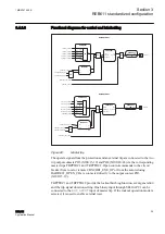
Figure 22:
Master trip
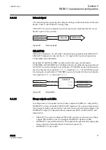
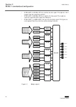
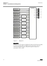
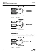
The operate signals from the protections and an external trip are connected to the two
trip output contacts PO3 (X100:15-19) and PO4 (X100:20-24) via the corresponding
master trips TRPPTRC1 and TRPPTRC2. Open control commands to the circuit
breaker from local or remote CBXCBR1_EXE_OP or from the autoreclosing
DARREC1_OPEN_CB are connected directly to the output contact PO3
(X100:15-19).
TRPPTRC1 and TRPPTRC2 provide the lockout/latching function, event generation
and the trip signal duration setting. One binary input through SELGAPC1 can be
connected to the
RST_LKOUT
input of master trip. If the lockout operation mode is
selected, it is used to enable external reset.
1MRS757455 E
Section 3
REB611 standardized configuration
REB611
39
Application Manual

