P
1
P
2
S
1
S
2
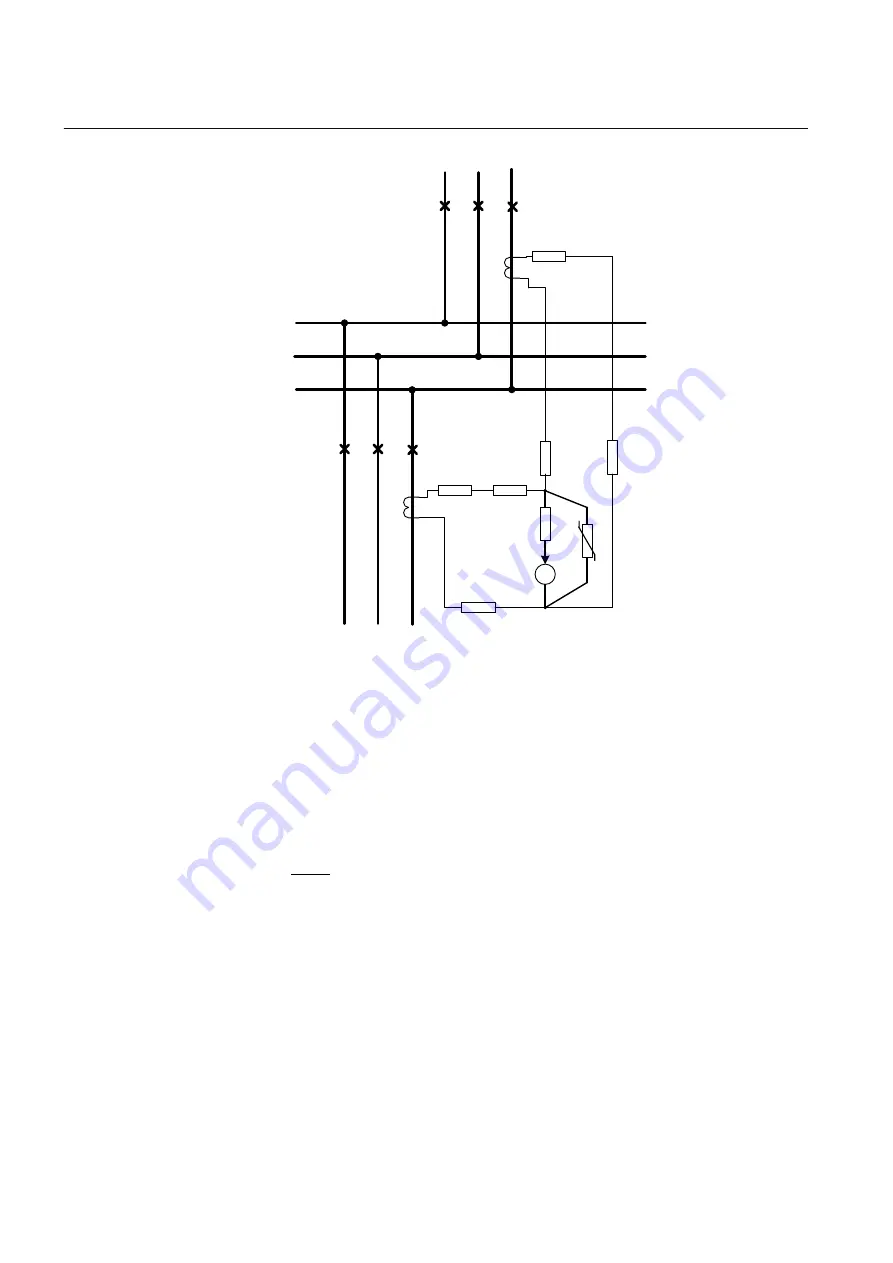
Incoming feeder
Outgoing feeder
Busbar
P
2
P
1
S
2
S
1
Phase A
Phase B
Phase C
R
s
I
d
R
u
3x required for
three phases
R
in1
= 1.2
Ω
R
in2
= 0.8
Ω
R
m1
= 2.0
Ω
R
m2
= 1.9
Ω
R
in1 +
R
m1
= 3.2
Ω
R
in2 +
R
m2
= 2.7
Ω
R
in1
R
m
1
/2
R
m
1
/2
R
m2
/2
R
m2
/2
R
in2
GUID-125D0534-32F1-4E09-8A34-CBF36D547735 V2 EN
Figure 54:
High-impedance busbar differential protection with different CT
burden value on each feeder
First, the stabilizing voltage, that is, the voltage appearing across the measuring
branch during the out-of-zone fault, is calculated assuming that one of the CTs
connected in parallel is fully saturated. The stabilizing voltage can be calculated using
the formula:
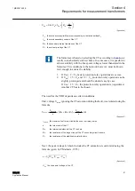
U
I
n
R
R
s
k
in
m
=
+
max
(
)
GUID-6A4C58E7-3D26-40C9-A070-0D99BA209B1A V1 EN
(Equation 1)
I
kmax
the highest through-fault current in primary amps. The highest earth-fault or short circuit current
during the out-of-zone fault.
n
the turns ratio of the CT
R
in
the secondary winding resistance of the CT in ohms
R
m
the total resistance of the secondary circuit wires in ohms
Section 4
1MRS757455 E
Requirements for measurement transformers
58
REB611
Application Manual

