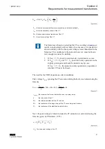
voltage-dependent resistor (VDR). The value of the primary current I
prim
at which the
protection relay operates at a certain setting can be calculated using the formula
I
n
I
I
m
I
prim
rs
u
m
= ×
+
+
×
(
)
GUID-2A742729-7244-4B1C-A4DF-404BDD3A68D9 V1 EN
(Equation 5)
I
prim
the primary current at which the protection is to start
n
the turn ratio of the current transformer
I
rs
the value of the
Operate value setting
I
u
the leakage current flowing through the VDR at the U
s
voltage
m
the number of current transformers included in the protection per phase
I
m
the magnetizing current per current transformer at the U
s
voltage
The I
e
value given in many catalogs is the excitation current at the knee point voltage.
Assuming U
kn
≈ 2 × U
s
, the value of
I
m
≈
I
e
2
gives an approximate value for
.
The selection of current transformers can be divided into procedures:
1. The rated current I
n
of the feeder should be known. The value of I
n
also affects
how high I
kmax
is.
2. The rated primary current I
1n
of the CT must be higher than the rated current of
the feeder.
The choice of the CT also specifies R
in
.
3. The required U
kn
. If U
kn
of the CT is not high
enough, enough, another CT has to be selected. The value of U
kn
is given by the
manufacturer in the case of Class X current transformers or it can be estimated
using
4. The sensitivity I
prim
is calculated using
. If the achieved sensitivity is
sufficient, the present CT is chosen. If a better sensitivity is needed, a CT with a
bigger core is chosen.
If other than Class X CTs are used, an estimate for U
kn
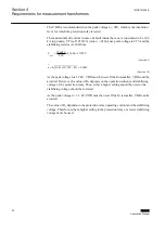
is calculated using the equation:
Section 4
1MRS757455 E
Requirements for measurement transformers
60
REB611
Application Manual

