background image

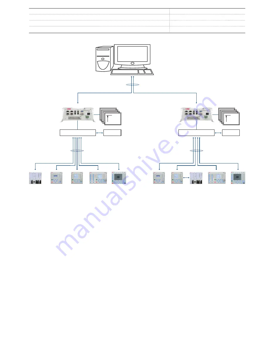
PCM600

Ethernet switch

Utility: IEC 60870-5-104

Industry: OPC

COM600S

Web HMI

ABB

MicroSCADA Pro/ 

System 800xA

Analog and binary horizontal  

GOOSE communication

IEC 61850

PCM600

Ethernet switch

COM600S

Web HMI

Analog and binary horizontal  

GOOSE communication

IEC 61850

GUID-4D002AA0-E35D-4D3F-A157-01F1A3044DDB V4 EN

Figure 5.

ABB power system example using Relion relays, COM600S and MicroSCADA Pro/System 800xA

6.  Control

REU615 integrates functionality for the control of a circuit
breaker via the front panel HMI or by means of remote controls.
In addition to the circuit breaker control the relay features two
control blocks which are intended for motor-operated control of
disconnectors or circuit breaker truck and for their position
indications.

Further, the relay offers one control block which is intended for
motor-operated control of one earthing switch control and its
position indication.

Two physical binary inputs and two physical binary outputs are
needed in the relay for each controllable primary device taken
into use. The number of unused binary inputs and binary
outputs varies depending on the chosen standard configuration
of the relay. Some standard configurations offer optional
hardware modules that increase the number of available binary
inputs and outputs.

If the amount of available binary inputs or outputs of the chosen
standard configuration is not sufficient, the standard

configuration can be modified to release some binary inputs or
outputs which have originally been configured for other
purposes, when applicable, or an external input or output
module, for example, RIO600 can be integrated to the relay.
The binary inputs and outputs of the external I/O module can be
used for the less time critical binary signals of the application.
The integration enables releasing of some initially reserved
binary inputs and outputs of the relay in the standard
configuration.

The suitability of the binary outputs of the relay which have been
selected for controlling of primary devices should be carefully
verified, for example the make and carry, as well as the breaking
capacity. If the requirements for the control-circuit of the
primary device are not met, the use of external auxiliary relays
should be considered.

The optional large graphical LCD of the relay's HMI includes a
single-line diagram (SLD) with position indication for the
relevant primary devices. Interlocking schemes required by the

Voltage Protection and Control

1MRS757058 K

REU615


Product version: 5.0 FP1


ABB

11

Summary of Contents for Relion 615 series

Page 1: ...RELION 615 SERIES Voltage Protection and Control REU615 Product Guide...

Page 2: ...d ordering data 43 24 Accessories and ordering data 44 25 Tools 45 26 Cyber security 46 27 Terminal diagrams 47 28 Certificates 49 29 References 49 30 Functions codes and symbols 50 31 Document revisi...

Page 3: ...cluding IEC 61850 with Edition 2 support process bus according to IEC 61850 9 2 LE IEC 60870 5 103 Modbus and DNP3 Profibus DPV1 communication protocol is supported by using the protocol converter SPA...

Page 4: ...upervision Analog interface types 1 Current transformer Voltage transformer 1 Conventional transformer inputs ALSO AVAILABLE Disturbance and fault recorders Event log and recorded data High Speed Outp...

Page 5: ...rnative function to be de ned when ordering Io Uo Calculated value 3 Sum of phase currents I Analog interface types 1 Current transformer Voltage transformer 1 Conventional transformer inputs ALSO AVA...

Page 6: ...regulator OLATCC 1 Synchronism and energizing check SECRSYN 1 Condition monitoring and supervision Trip circuit supervision TCSSCBR 2 2 Current circuit supervision CCSPVC 1 Fuse failure supervision S...

Page 7: ...al damage within the switchgear in an arc fault situation A binary input and output module can be selected as an option having three high speed binary outputs HSO it further decreases the total operat...

Page 8: ...EF 3Ith F ARC 3I 3I Io BF 3I Io Io IEF N REF615 Std conf ANSI IEC 49F 50L 50NL 50P 51P 51BF 51NBF 51P 51N 67NIEF 3Ith F ARC 3I 3I Io BF 3I Io Io IEF N REF615 Std conf ANSI IEC 49F 50L 50NL 50P 51P 51B...

Page 9: ...y measuring the oil and ambient temperature of the power transformer 5 Supported ABB solutions The 615 series protection relays together with the Substation Management Unit COM600S constitute a genuin...

Page 10: ...ates extensive reporting and analyzing of network fault situations by using the data historian and event handling features of COM600S The historical data can be used for accurate monitoring of process...

Page 11: ...lay Some standard configurations offer optional hardware modules that increase the number of available binary inputs and outputs If the amount of available binary inputs or outputs of the chosen stand...

Page 12: ...nce recorder featuring up to 12 analog and 64 binary signal channels The analog channels can be set to record either the waveform or the trend of the currents and voltages measured The analog channels...

Page 13: ...ity time of the circuit breaker The monitoring functions provide operational circuit breaker history data which can be used for scheduling preventive circuit breaker maintenance In addition the relay...

Page 14: ...ltage inputs The residual current input and the phase current inputs are rated 1 5 A The three phase voltage inputs and the residual voltage input covers the rated voltages 60 210 V Both phase to phas...

Page 15: ...ransformers In REU615 analog GOOSE messaging is employed in control schemes of parallel running transformers where measured values are exchanged between the relays The relay also supports IEC 61850 pr...

Page 16: ...ctions over the ring Every node forwards the frames it receives from one port to another to reach the next node When the originating sender node receives the frame it sent the sender node discards the...

Page 17: ...tch with standard Rapid Spanning Tree Protocol RSTP support The managed switch controls the consistency of the loop routes the data and corrects the data flow in case of a communication switch over Th...

Page 18: ...fferent masters Besides basic standard functionality the relay supports changing of the active setting group and uploading of disturbance recordings in IEC 60870 5 103 format Further IEC 60870 5 103 c...

Page 19: ...operation Required accuracy of grandmaster clock is 1 s The relay can work as a master clock per BMC algorithm if the external grandmaster clock is not available for short term The IEEE 1588 support i...

Page 20: ...ld 19 2 V DC 24 V DC 80 Burden of auxiliary voltage supply under quiescent Pq operating condition DC 13 0 W nominal 18 0 W max AC 16 0 W nominal 21 0 W max DC 13 0 W nominal 18 0 W max Ripple in the D...

Page 21: ...e three wire measurement 25 per lead Isolation 2 kV inputs to protective earth Response time 4 s RTD resistance sensing current Maximum 0 33 mA rms Operation accuracy Resistance Temperature 2 0 or 1 1...

Page 22: ...en the control circuit time constant L R 40 ms at 48 110 220 V DC two contacts connected in series 5 A 3 A 1 A Minimum contact load 100 mA at 24 V AC DC Trip circuit supervision TCS Control voltage ra...

Page 23: ...62 5 125 or 50 125 m glass fiber core 820 900 nm 1 km 11 dB 1 MM multi mode fiber SM single mode fiber 2 Maximum length depends on the cable attenuation and quality the amount of splices and connector...

Page 24: ...time service temperature range 40 85 C 16h 1 2 Relative humidity 93 non condensing Atmospheric pressure 86 106 kPa Altitude Up to 2000 m Transport and storage temperature range 40 85 C 1 Degradation...

Page 25: ...IEC 60255 26 class III 10 V m f 900 MHz ENV 50204 IEC 60255 26 class III 20 V m rms f 80 1000 MHz IEEE C37 90 2 2004 Fast transient disturbance test IEC 61000 4 4 IEC 60255 26 IEEE C37 90 1 2002 All...

Page 26: ...6 dB V m peak 56 dB V m average measured at 3 m distance 3 6 GHz 80 dB V m peak 60 dB V m average measured at 3 m distance Table 23 Insulation tests Description Type test value Reference Dielectric te...

Page 27: ...orage test 96 h at 40 C 96 h at 85 C IEC 60068 2 1 IEC 60068 2 2 1 For relays with an LC communication interface the maximum operating temperature is 70oC Table 26 Product safety Description Reference...

Page 28: ...P to P backup No suppression 1 Set Operate delay time 0 02 s Operate curve type IEC definite time Measurement mode default depends on stage current before fault 0 0 In fn 50 Hz fault current in one p...

Page 29: ...01 Operate delay time ROVPTOV 40 300000 ms 1 Table 33 Three phase undervoltage protection PHPTUV Characteristic Value Operation accuracy Depending on the frequency of the voltage measured fn 2 Hz 1 5...

Page 30: ...time mode 1 0 of the set value or 20 ms Operate time accuracy in inverse time mode 5 0 of the theoretical value or 20 ms3 Suppression of harmonics DFT 50 dB at f n fn where n 2 3 4 5 1 Start value 1 0...

Page 31: ...0 010 1 200 Un 0 001 Operate delay time PSPTUV 40 120000 ms 10 Voltage block value PSPTUV 0 01 1 00 Un 0 01 Table 39 Negative sequence overvoltage protection NSPTOV Characteristic Value Operation accu...

Page 32: ...0 200000 ms 10 Table 43 Three phase thermal overload protection two time constants T2PTTR Characteristic Value Operation accuracy Depending on the frequency of the measured current fn 2 Hz Current mea...

Page 33: ...Multipurpose protection MAPGAPC Characteristic Value Operation accuracy 1 0 of the set value or 20 ms Table 48 Multipurpose protection MAPGAPC main settings Parameter Function Value Range Step Start...

Page 34: ...1 Restore delay time LSHDPFRQ 80 200000 ms 10 Table 51 Operation characteristics Parameter Value Range Operating curve type 1 ANSI Ext inv 2 ANSI Very inv 3 ANSI Norm inv 4 ANSI Mod inv 5 ANSI Def Tim...

Page 35: ...Un Operation value 1 5 of the Ud for Us 1 0 Un Operate time accuracy in definite time mode2 4 0 0 of the set value Operate time accuracy in inverse time mode2 8 5 0 of the set value at theoretical B i...

Page 36: ...gle 3 Auto parallel 4 Input control 5 Command Custom Man blocking OLATCC 1 Custom disabled 2 OC 3 UV 4 OC UV 5 EXT 6 OC EXT 7 UV EXT 8 OC UV EXT Delay characteristics OLATCC 0 Inverse time 1 Definite...

Page 37: ...s L Any 5 Dead L Bus Any 6 One Live Dead 7 Not Both Live Difference voltage SECRSYN 0 01 0 50 Un 0 01 Difference frequency SECRSYN 0 001 0 100 fn 0 001 Difference angle SECRSYN 5 90 1 Synchrocheck mod...

Page 38: ...n UFault 1 1 set Neg Seq voltage Lev 33 ms UFault 5 0 set Neg Seq voltage Lev 18 ms Delta function U 1 1 set Voltage change rate 30 ms U 2 0 set Voltage change rate 24 ms 1 Includes the delay of the s...

Page 39: ...XU Characteristic Value Operation accuracy Depending on the frequency of the voltage measured fn 2 Hz At voltages in range 0 01 1 15 Un 0 5 or 0 002 Un Suppression of harmonics DFT 50 dB at f n fn whe...

Page 40: ...TD sensors 100 platinum 250 platinum 100 nickel 120 nickel 250 nickel 10 copper TCR 0 00385 DIN 43760 TCR 0 00385 TCR 0 00618 DIN 43760 TCR 0 00618 TCR 0 00618 TCR 0 00427 Supported resistance range 0...

Page 41: ...20 ms Table 70 Time delay off 8 pcs TOFPAGC Characteristic Value Operate time accuracy 1 0 of the set value or 20 ms Table 71 Time delay on 8 pcs TONGAPC Characteristic Value Operate time accuracy 1...

Page 42: ...y using the Graphical Display Editor in PCM600 The user can create up to 10 SLD pages The local HMI includes a push button L R for local remote operation of the relay When the relay is in the local mo...

Page 43: ...Figure 13 Semi flush mounting 230 107 25 133 190 IECA070902 V4 EN Figure 14 Semi flush mounting in a 25 tilt 22 Relay case and plug in unit The relay cases are assigned to a certain type of plug in un...

Page 44: ...ng bracket for one relay in 4U Combiflex RHGT 19 variant C 2RCA022643P0001 19 rack mounting kit for one relay and one RTXP18 test switch the test switch is not included in the delivery 2RCA021952A0003...

Page 45: ...e enabled via the local HMI The Web HMI functionality can be limited to read only access The relay connectivity package is a collection of software and specific relay information which enables system...

Page 46: ...nication configuration GOOSE communication configuration Phasor diagram viewing Event viewing Saving of event data on the user s PC Online monitoring Supported 26 Cyber security The relay supports rol...

Page 47: ...Terminal diagrams GUID B89BFFF3 08F0 40D3 8F12 99FB21B3900F V1 EN Figure 15 Terminal diagram of standard configuration A Voltage Protection and Control 1MRS757058 K REU615 Product version 5 0 FP1 ABB...

Page 48: ...GUID E5FA44B9 524F 4B19 A002 49D39DF6D6D5 V1 EN Figure 16 Terminal diagram of standard configuration B Voltage Protection and Control 1MRS757058 K REU615 Product version 5 0 FP1 48 ABB...

Page 49: ...5 1145 Additional certificates can be found on the product page 29 References The www abb com substationautomation portal provides information on the entire range of distribution automation products a...

Page 50: ...7 3 Three phase overvoltage protection PHPTOV1 3U 1 59 1 PHPTOV2 3U 2 59 2 PHPTOV3 3U 3 59 3 Positive sequence undervoltage protection PSPTUV1 U1 1 47U 1 PSPTUV2 U1 2 47U 2 Negative sequence overvolta...

Page 51: ...PFRQ2 UFLS R 2 81LSH 2 LSHDPFRQ3 UFLS R 3 81LSH 3 LSHDPFRQ4 UFLS R 4 81LSH 4 LSHDPFRQ5 UFLS R 5 81LSH 5 Control Circuit breaker control CBXCBR1 I O CB 1 I O CB 1 Disconnector control DCXSWI1 I O DCC 1...

Page 52: ...ement VSMSQI1 U1 U2 U0 1 V1 V2 V0 1 Three phase power and energy measurement PEMMXU1 P E 1 P E 1 RTD mA measurement XRGGIO130 X130 RTD 1 X130 RTD 1 Frequency measurement FMMXU1 f 1 f 1 IEC 61850 9 2 L...

Page 53: ...C1 MVI4 1 MVI4 1 31 Document revision history Document revision date Product version History A 2010 06 11 3 0 First release B 2010 06 29 3 0 Terminology updated C 2010 09 07 3 0 Content updated D 2012...

Page 54: ...54...

Page 55: ......

Page 56: ...01 VAASA Finland Phone 358 10 22 11 ABB Distribution Automation Maneja Works Vadodara 390013 India Phone 91 265 2604386 Fax 91 265 2638922 www abb com mediumvoltage www abb com relion www abb com subs...

Reviews: