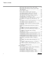
LD0.SPCGAPC1 Generic control point (16 pcs) (1) – SPC-1...... 64
LD0.TRPPTRC3 Master trip (3) – 86/94-3....................................65
LD0.TRPPTRC4 Master trip (4) – 86/94-4....................................65
LD0.TRPPTRC5 Master trip (5) – 86/94-5....................................66
LD0.UL1TVTR1 Three-phase VT supervision (1)........................ 66
LD0.XRGGIO130 Alarm/warning..................................................66
LD0.UDFCNT1 Multipurpose generic up-down counter (1) –
CTR-3...........................................................................................67
LD0.UDFCNT4 Multipurpose generic up-down counter (4) –
CTR-4...........................................................................................68
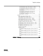
Premapped registers......................................................................... 68
Active parameter setting group - read and write...........................68
Control structure 1........................................................................69
Control structure 2........................................................................69
Control structure 3........................................................................69
Control structure 4........................................................................70
Control structure 5........................................................................70
Control structure 6........................................................................70
Control structure 7........................................................................71
Control structure 8........................................................................71
Device ID string............................................................................ 71
Event record structure.................................................................. 71
Fault record structure header....................................................... 76
Fault record data.......................................................................... 76
Protection relay's real-time clock (in local time mode) - read
and write (synchronize)................................................................ 80
Indication bits mirrored in registers...............................................81
SSR1 System status register (1) device health............................81
SSR2 System status register (2) protection relay's mode and
dependent)................................................................................... 82
SSR4 System status register (4) data available 2 (client-
dependent, user-definable)...........................................................83
Table of contents
REM615 ANSI
5
Point List Manual
Summary of Contents for Relion 615 series
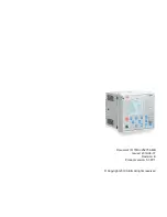
Page 1: ...RELION 615 SERIES Motor Protection and Control REM615 ANSI Modbus Point List Manual...
Page 2: ......
Page 14: ...8...
Page 114: ...108...


