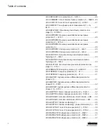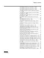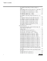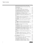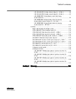
SSR5 System status register (5) device alive register................. 83
SSR6 System status register (6) control command status
(client-dependent).........................................................................84
System diagnostic values.............................................................84
Time and reason for latest protection relay reset......................... 85
User-definable bits [Alt.2], visible on 0x,1x,3x and 4x.................. 85
User-definable registers [Alt.1], visible on 3x and 4x....................86
CTRL.CBCSWI1 Circuit breaker operation counter (1) ............... 86
LD0.ARCSARCx1 Arc protection (x1) – AFD............................... 86
LD0.CMMXU1 Phase current demand values (1) – IA, IB, IC...... 87
LD0.CMMXU1 Three-phase current measurement (1) – IA,
IB, IC.............................................................................................88
LD0.CSMSQI1 Sequence current measurement (1) – I1, I2, I0... 88
LD0.FMMXU1 Frequency measurement (1) – f-1........................ 88
LD0.MDSOPT1 Runtime counter for machines and devices
49M-1........................................................................................... 89
LD0.PEMMTR1 Three-phase energy measurements (1).............89
LD0.PEMMXU1 Power measurement demand values (1) – P,
measurement (1) – P, E-1............................................................ 90
LD0.RESCMMXU1 Residual current demand value (1) – IG-1.... 91
LD0.RESCMMXU1 Residual current measurement (1) – IG-1.....91
LD0.RESVMMXU1 Residual voltage demand value (1) – VG-1.. 92
LD0.RESVMMXU1 Residual voltage measurement (1) – VG-1... 92
LD0.SSCBR1 Circuit-breaker condition monitoring (1) –
52CM-1.........................................................................................92
LD0.VMMXU1 Three-phase voltage measurement (1) – VA,
VB, VC..........................................................................................93
LD0.VMMXU1 Voltage demand values (1) – VA, VB, VC............ 94
LD0.VSMSQI1 Sequence voltage measurement (1) – V1, V2,
Unmapped registers.......................................................................... 95
CTRL.LLN0 Local, Remote, Station, Off and Combinations........ 95
LD0.LLN0/LPHD1/LDEV1 System values ...................................95
LD0.MVI4GAPC1 Integer value move (1) – MVI4-1..................... 95
LD0.SCA4GAPC1 Analog value scaling (1) – SCA4-1.................96
LD0.SCA4GAPC2 Analog value scaling (2) – SCA4-2.................96
Table of contents
6
REM615 ANSI
Point List Manual
Summary of Contents for Relion 615 series
Page 1: ...RELION 615 SERIES Motor Protection and Control REM615 ANSI Modbus Point List Manual...
Page 2: ......
Page 14: ...8...
Page 114: ...108...


