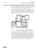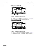
This mode catches a signal change to ON and the LED stays ON until the operator
resets the LEDs for this group.
If the signal is still ON when a reset LED is done, the LED will illuminate again. This
occurs when the application configuration accesses the signal again in the next cycle
after reset. The thin dashed lines in
shows the internal state of the LED
following the signal and reset, when no higher prior signal is given.
The LED illuminates always in steady mode.
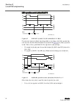
LED operation mode LatchedReset-S
IEC08000400.vsd
= Steady
= Flash
Illumination =>
Man-
Reset
S1
S2
S3
S4
tMax
tRestart
S1LED
S2LED
S3LED
S4LED
Auto-
Reset
IEC08000400 V1 EN
Figure 66:
LHMI: LED operation mode LatchedReset-S
This mode is useful to monitor signals that are involved in case of a disturbance, see
. The signal state after the disturbance allows a fast overview about the
disturbance. To get always the situation of the last occurred disturbance, the LEDs are
reset after a predefined time (tReset). So this is the longest time a disturbance can be
monitored by the LED situation.
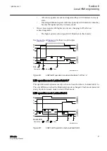
In case a second disturbance occurs before the tReset time has elapsed, see
the signals that are still ON at the end of tReset will return to ON with the next
application configuration cycle after tReset. To clear these LEDs, a second timer tMax
is used. TMax is started when the first signal of the disturbance changes to ON. tMax
is stopped, when tReset could clear all LEDs.
A disturbance runs for a maximum of some seconds, while tReset can be in the range
of 60 to 90 seconds.
The timer tReset and tMax are configured in Parameter Setting tool as part of the
function block LEDGEN.
Section 6
1MRS756800 F
Local HMI engineering
88
630 series
Engineering Manual


