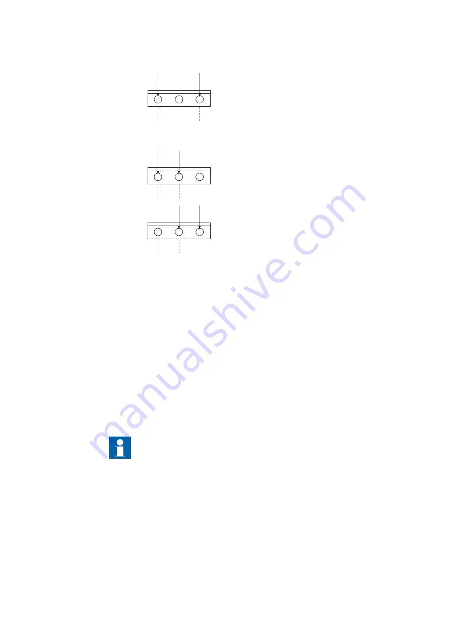
open
open
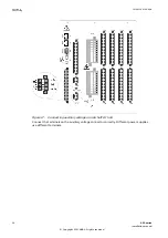
No damage will occur when the plug is inserted 180 degrees turned.
110-250 VDC
100-240 VAC
The input has a rectifier bridge
Correct / 180 degrees wrong
Correct
180 degrees wrong
No problem, contact open
48-125 VDC
1 2 3
1 2 3
1 2 3
GUID-C2321B6B-3157-4F0A-AD25-ACE8E71C4462 V2 EN-US
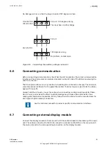
Figure 18: Connecting the auxiliary voltage connector
6.6
Connecting communication
GUID-ABE5A9D7-4292-4AE3-A8B7-0C52F54E754E v7
Before connecting communication, check that the HW module has the correct communication
interfaces. The communication module is located on the left side of the IED when viewing the
case from the rear.
The fiber optical cables are very sensitive to handling. Do not bend too sharply. The minimum
curvature radius is 250 mm for the glass fiber cables. If cable straps are used to fix the cables,
apply with loose fit.
Always hold the connector, never the cable, when connecting or disconnecting optical fibers.
Do not twist, pull or bend the fiber. Invisible damage may increase fiber attenuation thus
making communication impossible. Strictly follow the instructions from the manufacturer for
each type of optical cables/connectors.
See the technical manual for product-specific communication interfaces.
6.7
Connecting external display module
GUID-98491CB2-66DE-4ACB-80DA-B6D76998880F v2
Connect the display module to the main unit with the cable included in the delivery of the main
unit. The cable is connected to the RJ-45 connection (connector X0/HMI) on the rear panel of
the main unit and to the corresponding connection on the display module.
1MRK 514 014-UEN A
Section 6
Connecting
650 series
35
Installation manual
© Copyright 2011 ABB. All rights reserved

