en06000104.vsd
AP
Subnetwork
Control
IED
CVMMXU1
SB1.LD0
Server
LPHD
SXCBR1
SCSWI1
SXSWI1
SCSWI2
SXSWI2
SCSWI3
SXSWI3
SCSWI4
SXSWI4
SCSWI5
LLN0
Mod
CBOpCap
Origin
Data
Data
Attribute
Beh
Health
NamePlt
ctlVal
Pos
Loc
OpCnt
BlkOpn
BlkCls
stVal
q
t
Logical
Node
ctlModel
IEC06000104 V2 EN
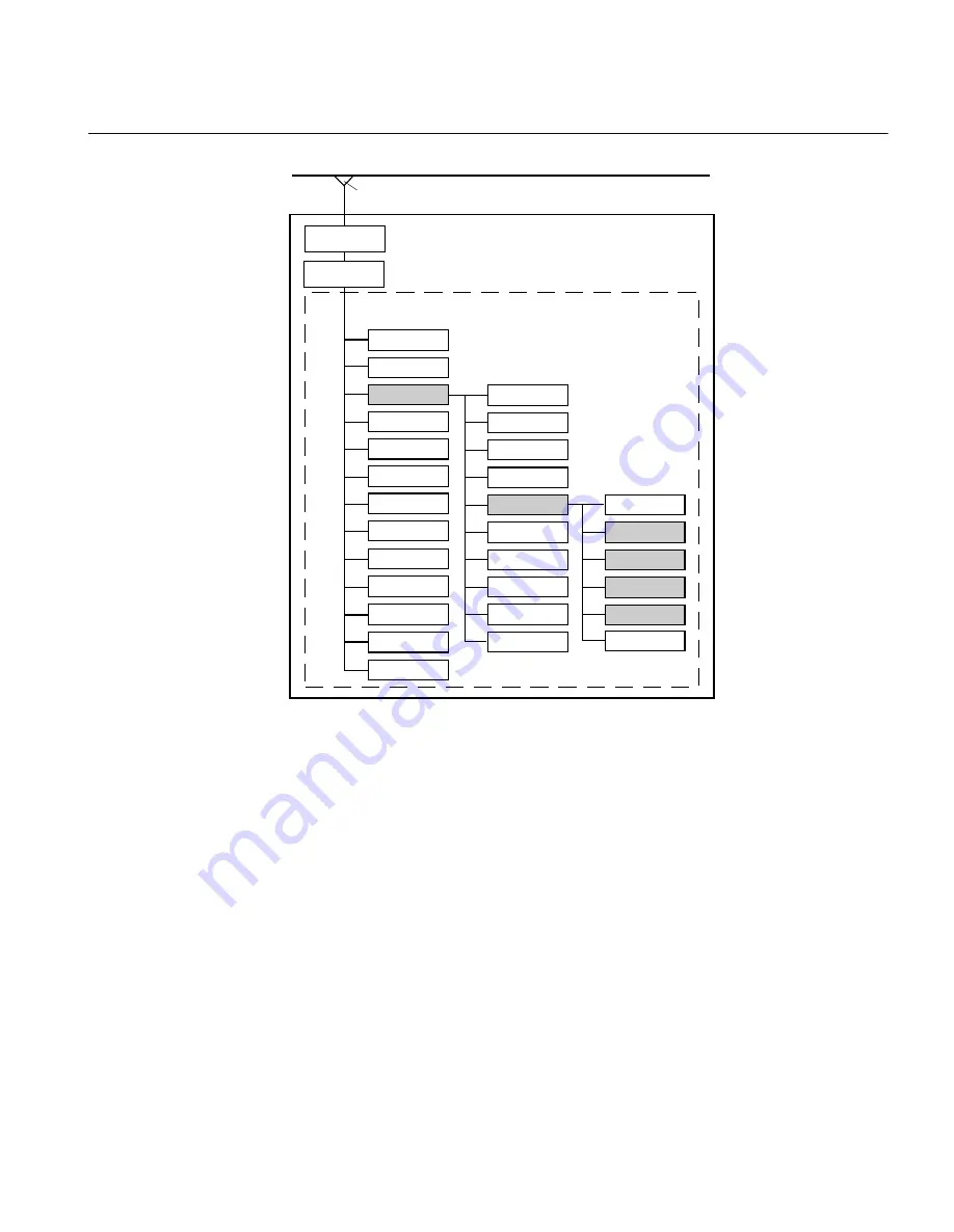
Figure 4:
Organization of LDs, LNs, DOs and DAs in an IED
•
A server represents the communication interface to the subnetwork (Ethernet).
•
One or more logical device(s) (LD) are connected to a server.
•
A set of logical nodes belong to a LD.
•
The LN LLN0 is a special logical node per LD and contains for example the data sets,
the various control blocks, inputs (from GOOSE messages). In IED 650 series, the
data sets and the control blocks shall be located to LD0.
•
The LN LPHD is a special logical node per LD and contains data objects that describe
the status of the physical device (the IED)
•
Each logical node represents a function and contains a number of data objects (DO)
•
Each DO includes a number of data attributes (DA)
The data objects represent information signals that may be routed to station level IEDs or
to other bay IEDs that are communicating via GOOSE. The signal engineering task is to
1MRK 511 281-UUS A
Section 3
Substation Configuration description Language (SCL)
650 series ANSI
29
Communication protocol manual
Summary of Contents for Relion 650 series ANSI
Page 1: ...Relion Protection and Control 650 series ANSI IEC 61850 Communication protocol manual ...
Page 2: ......
Page 13: ...Section 9 Glossary 227 Table of contents 650 series ANSI 7 Communication protocol manual ...
Page 14: ...8 ...
Page 26: ...20 ...
Page 44: ...38 ...
Page 226: ...220 ...
Page 241: ...235 ...


