background image

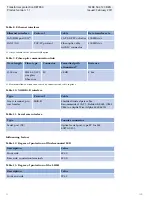
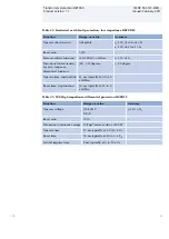
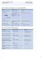
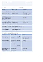
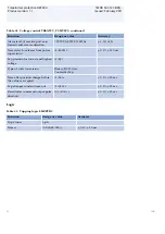
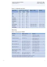
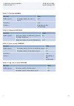
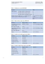
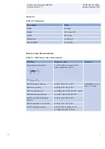
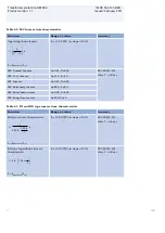
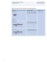
Table 32. Negative sequence based overcurrent function DNSPTOC

Function

Range or value

Accuracy

Operate current

(2.0 - 5000.0) % of 

IBase

± 1.0% of I

r

 at I <I

r

± 1.0% of I at I > I

r

Reset ratio

> 95 %

-

Low voltage level for memory (0.0 - 5.0) % of 

UBase

< ± 0,5% of U

r

Relay characteristic angle

(-180 - 180) degrees

± 2,0 degrees

Relay operate angle

(1 - 90) degrees

± 2,0 degrees

Timers

(0.00 - 6000.00) s

± 0.5% ± 25 ms

Operate time, non-directional 30 ms typically at 0 to 2 x I

set

20 ms typically at 0 to 10 x I

set

-

Reset time, non-directional

40 ms typically at 2 to 0 x I

set

-

Operate time, directional

30 ms typically at 0 to 2 x I

set

20 ms typically at 0 to 10 x I

set

-

Reset time, directional

40 ms typically at 2 to 0 x I

set

-

Critical impulse time

10 ms typically at 0 to 2 x I

set

2 ms typically at 0 to 10 x I

set

-

Impulse margin time

15 ms typically

-

Dynamic overreach

< 10% at t = 300 ms

-

Transformer protection RET650

1MRK 504 127-BEN -

Product version: 1.1

Issued: February 2011

56

ABB

Summary of Contents for Relion 650 series RET650

Page 1: ...Relion 650 series Transformer protection RET650 Product Guide ...

Page 2: ...diagrams 30 18 Technical data 37 19 Ordering 73 Disclaimer The information in this document is subject to change without notice and should not be construed as a commitment by ABB AB ABB AB assumes no responsibility for any errors that may appear in this document Copyright 2011 ABB AB All rights reserved Trademarks ABB and Relion are registered trademarks of ABB Group All other brand or product nam...

Page 3: ...lications Since RET650 has very low requirements on the main CTs no interposing CTs are required The differential protection function is provided with 2nd harmonic and wave block restraint features to avoid tripping for magnetizing inrush current and 5th harmonic restraint to avoid tripping for overexcitation The differential function offers a high sensitivity for low level internal faults The uni...

Page 4: ... winding transformer in single breaker arrangements A05 Tap changer control A07 The packages are configured and ready for direct use Analog and tripping IO has been pre defined for basic use Other signals need to be applied as required for each application The graphical configuration tool ensures simple and fast testing and commissioning Transformer protection RET650 1MRK 504 127 BEN Product versi...

Page 5: ...d functions REF PDIF 87N IdN I EF4 PTOC 51N 67N IN DRP RDRE Mont Y Y ROV2 PTOV 59N 3U0 RET650 A01 2 Winding Transformer protection 10AI 8I 2U 20 MVA 110 11 1 5 21 kV 105 550 A YNd5 20 kV Bus 110 kV Bus 200 1 600 1 20kV 100V 200 1 600 1 IEC61850 ANSI IEC Function Enabled in Settings IEC61850 ANSI IEC Function Disabled in Settings W1 W2 IEC09000645 2 en vsd IEC09000645 V2 EN Figure 1 A typical prote...

Page 6: ...R 49 Ith REF PDIF 87N IdN I Other configured functions REF PDIF 87N IdN I REF PDIF 87N IdN I OEX PVPH 24 U f OC4 PTOC 51 67 3I EF4 PTOC 51N 67N IN EF4 PTOC 51N 67N IN DRP RDRE Mont CV MMXN Meter Y Y ROV2 PTOV 59N 3UO 35 kV Bus 110 kV Bus 10 kV Bus IEC61850 ANSI IEC Function Enabled in Settings IEC61850 ANSI IEC Function Disabled in Settings Transformer Data 40 40 15 MVA 110 11 1 5 36 75 10 5 kV 21...

Page 7: ...84 TCM YLTC 84 TCS SCBR Cond TCS SCBR Cond SPVN ZBAT Cond Other configured functions DRP RDRE Mont T1 Data 20 MVA 110 11 1 5 21 kV 105 550 A YNd5 XT 11 T2 Data 20 MVA 110 11 1 5 21 kV 105 550 A YNd5 XT 11 20 kV Bus 1 20 kV Bus 2 IEC61850 ANSI IEC Function Enabled in Settings IEC61850 ANSI IEC Function Disabled in Settings 600 1 20kV 100V 600 1 20kV 100V W2 W2 IEC09000647 2 en vsd IEC09000647 V2 EN...

Page 8: ...TC Differential protection T2WPDIF 87T Transformer differential protection two winding 1 T3WPDIF 87T Transformer differential protection three winding 1 REFPDIF 87N Restricted earth fault protection low impedance 2 3 HZPDIF 87 1Ph High impedance differential protection 2 2 Transformer protection RET650 1MRK 504 127 BEN Product version 1 1 Issued February 2011 8 ABB ...

Page 9: ...TR 49 Thermal overload protection two time constants 2 3 2 CCRBRF 50BF Breaker failure protection 2 3 CCRPLD 52PD Pole discordance protection 2 3 GUPPDUP 37 Directional underpower protection 1 1 2 GOPPDOP 32 Directional overpower protection 1 1 2 DNSPTOC 46 Negative sequence based overcurrent function 1 2 Voltage protection UV2PTUV 27 Two step undervoltage protection 1 1 2 OV2PTOV 59 Two step over...

Page 10: ...50 A01 2W 1CB RET650 A05 3W 1CB RET650 A07 OLTC SAPTUF 81 Underfrequency function 4 4 4 SAPTOF 81 Overfrequency function 4 4 4 SAPFRC 81 Rate of change frequency protection 2 2 4 Transformer protection RET650 1MRK 504 127 BEN Product version 1 1 Issued February 2011 10 ABB ...

Page 11: ... 15 VSGGIO Selector mini switch extension 20 20 20 DPGGIO IEC 61850 generic communication I O functions double point 16 16 16 SPC8GGIO Single point generic control 8 signals 5 5 5 AUTOBITS AutomationBits command function for DNP3 0 3 3 3 I103CMD Function commands for IEC60870 5 103 1 1 1 I103IEDCMD IED commands for IEC60870 5 103 1 1 1 I103USRCMD Function commands user defined for IEC60870 5 103 4...

Page 12: ...p delay 40 40 40 TIMERSET Configurable logic blocks timer function block 40 40 40 AND Configurable logic blocks AND gate 280 280 280 SRMEMORY Configurable logic blocks set reset memory flip flop gate 40 40 40 RSMEMORY Configurable logic blocks reset set memory flip flop gate 40 40 40 FXDSIGN Fixed signal function block 1 1 1 B16I Boolean 16 to Integer conversion 16 16 16 B16IFCVI Boolean 16 to Int...

Page 13: ...tions 64 64 64 SP16GGIO IEC 61850 generic communication I O functions 16 inputs 16 16 16 MVGGIO IEC 61850 generic communication I O functions 16 16 16 MVEXP Measured value expander block 66 66 66 SPVNZBAT Station battery supervision 1 1 1 SSIMG 63 Insulation gas monitoring function 2 2 2 SSIML 71 Insulation liquid monitoring function 2 2 2 SSCBR Circuit breaker condition monitoring 2 3 2 I103MEAS ...

Page 14: ...03 1 1 1 I103IED IED status for IEC60870 5 103 1 1 1 I103SUPERV Supervison status for IEC60870 5 103 1 1 1 I103USRDEF Status for user defined signals for IEC60870 5 103 20 20 20 Metering PCGGIO Pulse counter logic 16 16 16 ETPMMTR Function for energy calculation and demand handling 3 3 3 Transformer protection RET650 1MRK 504 127 BEN Product version 1 1 Issued February 2011 14 ABB ...

Page 15: ... GOOSEBINRCV GOOSE binary receive 4 4 4 GOOSEVCTRCONF GOOSE VCTR configuration for send and receive 1 1 1 VCTRSEND Voltage control sending block for GOOSE 1 1 1 GOOSEVCTRRCV Voltage control receiving block for GOOSE 3 3 3 GOOSEDPRCV GOOSE function block to receive a double point value 32 32 32 GOOSEINTRCV GOOSE function block to receive an integer value 32 32 32 GOOSEMVRCV GOOSE function block to ...

Page 16: ...g groups 1 TESTMODE Test mode functionality 1 CHNGLCK Change lock function 1 TERMINALID IED identifiers 1 PRODINF Product information 1 PRIMVAL Primary system values 1 SMAI_20_1 12 Signal matrix for analog inputs 2 3PHSUM Summation block 3 phase 12 GBASVAL Global base values for settings 6 ATHSTAT Authority status 1 ATHCHCK Authority check 1 FTPACCS FTP access with password 1 DOSFRNT Denial of ser...

Page 17: ...ed for system recovery inrush and CT saturation for external faults A high set unrestrained differential current protection is included for a very high speed tripping at a high internal fault currents An innovative sensitive differential protection feature based on the theory of symmetrical components offers the best possible coverage for power transformer winding turn to turn faults Restricted ea...

Page 18: ...PTOC has a settable inverse or definite time delay independent for step 1 and 4 separately Step 2 and 3 are always definite time delayed All IEC and ANSI time delayed characteristics are available The directional function is voltage polarized current polarized or dual polarized EF4PTOC can be set directional or non directional independently for each of the steps A second harmonic blocking can be s...

Page 19: ...ectional over under power protection GOPPDOP GUPPDUP can be used wherever a high low active reactive or apparent power protection or alarming is required The functions can alternatively be used to check the direction of active or reactive power flow in the power system There are a number of applications where such functionality is needed Some of them are detection of reversed active power flow det...

Page 20: ...to carry flux and cause eddy currents to flow The eddy currents can cause excessive heating and severe damage to insulation and adjacent parts in a relatively short time The function has settable inverse operating curves and independent alarm stages 7 Frequency protection Underfrequency protection SAPTUF Underfrequency occurs as a result of lack of generation in the network Underfrequency protecti...

Page 21: ...rs with a motor driven load tap changer The functions provide automatic regulation of the voltage on the secondary side of transformers or alternatively on a load point further out in the network Control of a single transformer as well as control of up to two transformers within a single RET650 or parallel control of up to four transformers in two separate RET650 is possible Note that the last alt...

Page 22: ...ation that do not need extensive command receiving functionality for example SCSWI In this way simple commands can be sent directly to the IED outputs without confirmation Confirmation status of the result of the commands is supposed to be achieved by other means such as binary inputs and SPGGIO function blocks The commands can be pulsed or steady AutomationBits AUTOBITS The Automation bits functi...

Page 23: ...6IFCVI is used to transform a set of 16 binary logical signals into an integer Integer to Boolean 16 conversion IB16A Integer to boolean 16 conversion function IB16A is used to transform an integer into a set of 16 binary logical signals Integer to Boolean 16 conversion with logic node representation IB16FCVB Integer to boolean conversion with logic node representation function IB16FCVB is used to...

Page 24: ...y signals that have changed status during a disturbance This information is used in the short perspective to get information via the local HMI in a straightforward way There are three LEDs on the local HMI green yellow and red which will display status information about the IED and the Disturbance report function trigged The Indication list function shows all selected binary input signals connecte...

Page 25: ...e high high limit or above high limit The output signals can be used as conditions in the configurable logic or for alarming purpose Station battery supervision SPVNZBAT The station battery supervision function SPVNZBAT is used for monitoring battery terminal voltage SPVNZBAT activates the start and alarm outputs when the battery terminal voltage exceeds the set upper limit or drops below the set ...

Page 26: ... function 13 Human Machine interface Local HMI GUID 23A12958 F9A5 4BF1 A31B F69F56A046C7 V2 EN Figure 6 Local human machine interface The LHMI of the IED contains the following elements Display LCD Buttons LED indicators Communication port The LHMI is used for setting monitoring and controlling The Local human machine interface LHMI includes a graphical monochrome LCD with a resolution of 320x240 ...

Page 27: ...of sources SNTP IRIG B DNP IEC60870 5 103 Parameter setting groups ACTVGRP Use the four sets of settings to optimize the IED operation for different system conditions Creating and switching between fine tuned setting sets either from the local HMI or configurable binary inputs results in a highly adaptable IED that can cope with a variety of system scenarios Test mode functionality TESTMODE The pr...

Page 28: ... example from MMXU functions together with their quality using the IEC 61850 8 1 GOOSE profile The IED meets the GOOSE performance requirements for tripping applications in substations as defined by the IEC 61850 standard The IED interoperates with other IEC 61850 compliant IEDs tools and systems and simultaneously reports events to five different clients on the IEC 61850 station bus The event sys...

Page 29: ... primary station is a master and a secondary station is a slave The communication is based on a point to point principle The master must have software that can interpret IEC 60870 5 103 communication messages 16 Hardware description Layout and dimensions Mounting alternatives The following mounting alternatives are available IP40 protection from the front 19 rack mounting kit Wall mounting kit Flu...

Page 30: ...g lug connector B 25 5 mm C 482 6 mm 19 D 13 mm E 265 9 mm 6U Wall mounting the IED C F G B A E D IEC09000678 ai IEC09000678 V1 EN Figure 11 Wall mounting the IED A 270 mm E 190 5 mm B 252 5 mm F 296 mm C 6 8 mm G 13 mm D 268 9 mm GUID 5C185EAC 13D0 40BD 8511 58CA53EFF7DE V1 EN Figure 12 Main unit and detached LHMI display A 25 5 mm E 258 6 mm B 220 mm F 265 9 mm C 13 mm G 224 mm D 265 9 mm Transf...

Page 31: ...r 6U 1 2x19 casing with 1 TRM and 1 AIM A05 Module Slot Rear Position COM pCOM X0 X1 X4 X9 X304 PSM pPSM X307 X309 X410 TRM p2 X101 X102 AIM p4 X103 X104 BIO p5 X331 X334 BIO p6 X336 X339 Transformer protection RET650 1MRK 504 127 BEN Product version 1 1 Issued February 2011 ABB 31 ...

Page 32: ...g with 1 TRM A01 A07 Module Slot Rear Position COM pCOM X0 X1 X4 X9 X304 PSM pPSM X307 X309 X410 TRM p2 X101 X102 BIO p3 X321 X324 BIO p4 X326 X329 BIO p5 X331 X334 BIO p6 X336 X339 Transformer protection RET650 1MRK 504 127 BEN Product version 1 1 Issued February 2011 32 ABB ...

Page 33: ...6501 GB 4 PG 1 1 IEC V1 EN Figure 16 Power supply module PSM 48 125V DC 1MRK006501 GB 5 PG 1 1 IEC V1 EN Figure 17 Power supply module PSM 110 250V DC 1MRK006501 GB 6 PG 1 1 IEC V1 EN Figure 18 Transformer module TRM Transformer protection RET650 1MRK 504 127 BEN Product version 1 1 Issued February 2011 ABB 33 ...

Page 34: ...re 20 Binary input output BIO option Terminal X326 X329 Connection diagrams for RET650 A05 1MRK006501 FB 3 PG 1 1 IEC V1 EN Figure 21 Communication module COM 1MRK006501 FB 4 PG 1 1 IEC V1 EN Figure 22 Power supply module PSM 48 125V DC Transformer protection RET650 1MRK 504 127 BEN Product version 1 1 Issued February 2011 34 ABB ...

Page 35: ... 1 IEC V1 EN Figure 24 Transformer module TRM 1MRK006501 FB 7 PG 1 1 IEC V1 EN Figure 25 Analog input module AIM 1MRK006501 FB 8 PG 1 1 IEC V1 EN Figure 26 Binary input output BIO option Terminal X331 X334 Transformer protection RET650 1MRK 504 127 BEN Product version 1 1 Issued February 2011 ABB 35 ...

Page 36: ... A07 1MRK006501 EB 3 PG 1 1 IEC V1 EN Figure 28 Communication module COM 1MRK006501 EB 4 PG 1 1 IEC V1 EN Figure 29 Power supply module PSM 48 125V DC 1MRK006501 EB 5 PG 1 1 IEC V1 EN Figure 30 Power supply module PSM 110 250V DC Transformer protection RET650 1MRK 504 127 BEN Product version 1 1 Issued February 2011 36 ABB ...

Page 37: ...6501 EB 7 PG 1 1 IEC V1 EN Figure 32 Binary input output BIO option Terminal X321 X324 1MRK006501 EB 8 PG 1 1 IEC V1 EN Figure 33 Binary input output BIO option Terminal X326 X329 Transformer protection RET650 1MRK 504 127 BEN Product version 1 1 Issued February 2011 ABB 37 ...

Page 38: ...within which under specified conditions the equipment meets the specified requirements Operative range The range of values of a given energizing quantity for which the equipment under specified conditions is able to perform its intended functions according to the specified requirements Energizing quantities rated values and limits Transformer protection RET650 1MRK 504 127 BEN Product version 1 1 ...

Page 39: ... s 100 A 500 A For 10 s 20 A 100 A Dynamic current withstand Half wave value 250 A 1250 A Input impedance 100 mΩ 20 mΩ Voltage inputs Rated voltage Un 100 V AC 110 V AC 115 V AC 120 V AC Voltage withstand Continuous 420 V rms For 10 s 450 V rms Burden at rated voltage 0 05 VA 1 Residual current 2 Phase currents or residual current Transformer protection RET650 1MRK 504 127 BEN Product version 1 1 ...

Page 40: ...tage Max 15 of the DC value at frequency of 100 Hz Maximum interruption time in the auxiliary DC voltage without resetting the IED 50 ms at Uaux Binary inputs and outputs Table 4 Binary inputs Description Value Operating range Maximum input voltage 300 V DC Rated voltage 24 250 V DC Current drain 1 6 1 8 mA Power consumption input 0 3 W Threshold voltage 15 221 V DC parametrizable in the range in ...

Page 41: ...y for 3 0 s 15 A Make and carry for 0 5 s 30 A Breaking capacity when the control circuit time constant L R 40 ms at U 48 110 220 V DC 1 A 0 3 A 0 1 A Table 7 Power output relays with TCS function Description Value Rated voltage 250 V DC Continuous contact carry 8 A Make and carry for 3 0 s 15 A Make and carry for 0 5 s 30 A Breaking capacity when the control circuit time constant L R 40 ms at U 4...

Page 42: ... connectors and cable together Table 10 X4 IRIG B interface Type Protocol Cable Screw terminal pin row header IRIG B Shielded twisted pair cable Recommended CAT 5 Belden RS 485 9841 9844 or Alpha Wire Alpha 6222 6230 Table 11 Serial rear interface Type Counter connector Serial port X9 Optical serial port type ST for IEC 60870 5 103 Influencing factors Table 12 Degree of protection of flush mounted...

Page 43: ...de up to 2000 m Transport and storage temperature range 40 85ºC Table 15 Environmental tests Description Type test value Reference Cold tests operation storage 96 h at 25ºC 16 h at 40ºC 96 h at 40ºC IEC 60068 2 1 Dry heat tests operation storage 16 h at 70ºC 96 h at 85ºC IEC 60068 2 2 Damp heat tests steady state cyclic 240 h at 40ºC humidity 93 6 cycles at 25 to 55ºC humidity 93 95 IEC 60068 2 78...

Page 44: ...0 V emf f 150 kHz 80 MHz IEC 61000 4 6 IEC 60255 22 6 level 3 Radiated amplitude modulated 20 V m rms f 80 1000 MHz and f 1 4 2 7 GHz IEC 61000 4 3 IEC 60255 22 3 level 3 Fast transient disturbance tests IEC 61000 4 4 IEC 60255 22 4 class A Communication ports 2 kV Other ports 4 kV Surge immunity test IEC 61000 4 5 IEC 60255 22 5 level 3 2 Communication 1 kV line to earth Other ports 2 kV line to ...

Page 45: ...start 0 s Correct behaviour at power down IEC 60255 11 IEC 61000 4 11 Electromagnetic emission tests EN 55011 class A IEC 60255 25 Conducted RF emission mains terminal 0 15 0 50 MHz 79 dB µV quasi peak 66 dB µV average 0 5 30 MHz 73 dB µV quasi peak 60 dB µV average Radiated RF emission 30 230 MHz 40 dB µV m quasi peak measured at 10 m distance 230 1000 MHz 47 dB µV m quasi peak measured at 10 m d...

Page 46: ...100 MΏ 500 V DC Protective bonding resistance IEC 60255 27 Resistance 0 1 Ώ 60 s Table 18 Mechanical tests Description Reference Requirement Vibration response tests sinusoidal IEC 60255 21 1 Class 2 Vibration endurance test IEC60255 21 1 Class 1 Shock response test IEC 60255 21 2 Class 1 Shock withstand test IEC 60255 21 2 Class 1 Bump test IEC 60255 21 2 Class 1 Seismic test IEC 60255 21 3 Class...

Page 47: ...ance Table 20 EMC compliance Description Reference EMC directive 2004 108 EC Standard EN 50263 2000 EN 60255 26 2007 Transformer protection RET650 1MRK 504 127 BEN Product version 1 1 Issued February 2011 ABB 47 ...

Page 48: ...0 degrees Second harmonic blocking 5 0 100 0 of fundamental differential current 2 0 of Ir Fifth harmonic blocking 5 0 100 0 of fundamental differential current 12 0 of Ir Connection type for each of the windings Y or D Phase displacement between high voltage winding W1 and each of the windings W2 and W3 Hour notation 0 11 Operate time restrained function 25 ms typically at 0 to 5 x Ib Reset time ...

Page 49: ...ip function 25 ms typically at 0 to 10 x IdMin Reset time trip function 30 ms typically at 10 to 0 x IdMin Table 23 1Ph High impedance differential protection HZPDIF Function Range or value Accuracy Operate voltage 20 400 V I U R 1 0 of Ir Reset ratio 95 Maximum continuous voltage U Trip2 series resistor 200 W Operate time 15 ms typically at 0 to 10 x Ud Reset time 90 ms typically at 10 to 0 x Ud ...

Page 50: ... 20 ms typically at 0 to 2 x Iset Reset time 35 ms typically at 2 to 0 x Iset Critical impulse time 10 ms typically at 0 to 2 x Iset Operate time 10 ms typically at 0 to 10 x Iset Reset time 45 ms typically at 10 to 0 x Iset Critical impulse time 2 ms typically at 0 to 10 x Iset Dynamic overreach 5 at t 100 ms Transformer protection RET650 1MRK 504 127 BEN Product version 1 1 Issued February 2011 ...

Page 51: ...racteristics see table 61 table 62 and table 63 17 curve types See table 61 table 62 and table 63 Operate time nondirectional start function 20 ms typically at 0 to 2 x Iset Reset time nondirectional start function 30 ms typically at 2 to 0 x Iset Operate time directional start function 30 ms typically at 0 to 2 x Iset Reset time directional start funciton 25 ms typically at 2 to 0 x Iset Critical...

Page 52: ...ypically at 0 to 2 x Iset Reset time 30 ms typically at 2 to 0 x Iset Critical impulse time 10 ms typically at 0 to 2 x Iset Operate time 10 ms typically at 0 to 10 x Iset Reset time 40 ms typically at 10 to 0 x Iset Critical impulse time 2 ms typically at 0 to 10 x Iset Dynamic overreach 5 at t 100 ms Transformer protection RET650 1MRK 504 127 BEN Product version 1 1 Issued February 2011 52 ABB ...

Page 53: ... types See table 61 table 62 and table 63 Minimum polarizing voltage 1 100 of UBase 0 5 of Ur Minimum polarizing current 2 100 of IBase 1 0 of Ir Real part of source Z used for current polarization 0 50 1000 00 W phase Imaginary part of source Z used for current polarization 0 50 3000 00 W phase Operate time non directional start function 30 ms typically at 0 5 to 2 x Iset Reset time non direction...

Page 54: ...10 95 of heat content trip 2 0 of heat content trip Table 29 Breaker failure protection CCRBRF Function Range or value Accuracy Operate phase current 5 200 of lBase 1 0 of Ir at I Ir 1 0 of I at I Ir Reset ratio phase current 95 Operate residual current 2 200 of lBase 1 0 of Ir at I Ir 1 0 of I at I Ir Reset ratio residual current 95 Phase current level for blocking of contact function 5 200 of lB...

Page 55: ... level 0 0 500 0 of SBase 1 0 of Sr at S Sr 1 0 of S at S Sr 1 1 0 2 0 of SBase 50 of set value 2 2 0 10 of SBase 20 of set value 3 Characteristic angle 180 0 180 0 degrees 2 degrees Timers 0 010 6000 000 s 0 5 25 ms 1 Accuracy valid for 50 Hz At 60 Hz both accuracies are 2 0 2 Accuracy valid for 50 Hz At 60 Hz the accuracy is 50 100 3 Accuracy valid for 50 Hz At 60 Hz the accuracy is 40 Transform...

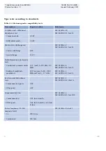
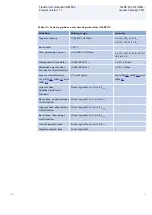
Page 56: ...5 25 ms Operate time non directional 30 ms typically at 0 to 2 x Iset 20 ms typically at 0 to 10 x Iset Reset time non directional 40 ms typically at 2 to 0 x Iset Operate time directional 30 ms typically at 0 to 2 x Iset 20 ms typically at 0 to 10 x Iset Reset time directional 40 ms typically at 2 to 0 x Iset Critical impulse time 10 ms typically at 0 to 2 x Iset 2 ms typically at 0 to 10 x Iset ...

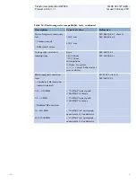
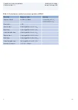
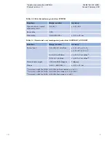
Page 57: ... at 2 to 0 x Uset Impulse margin time 15 ms typically Table 34 Two step overvoltage protection OV2PTOV Function Range or value Accuracy Operate voltage low and high step 1 200 of UBase 0 5 of Ur at U Ur 0 5 of U at U Ur Reset ratio 95 Inverse time characteristics for low and high step see table 64 See table 64 Definite time delay step 1 0 00 6000 00 s 0 5 25 ms Definite time delays step 2 0 000 60...

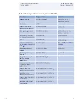
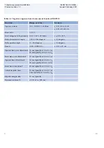
Page 58: ... 30 ms typically at 0 to 2 x Uset Reset time start function 40 ms typically at 2 to 0 x Uset Critical impulse time 10 ms typically at 0 to 2 x Uset Impulse margin time 15 ms typically Table 36 Overexcitation protection OEXPVPH Function Range or value Accuracy Operate value start 100 180 of UBase frated 0 5 of U Operate value alarm 50 120 of start level 0 5 of Ur at U Ur 0 5 of U at U Ur Operate va...

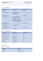
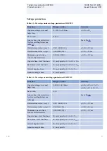
Page 59: ...50 ms typically at fset 0 5 Hz to fset 0 5 Hz Operate time delay 0 000 60 000 s 250 ms Restore time delay 0 000 60 000 s 150 ms Table 38 Overfrequency protection SAPTOF Function Range or value Accuracy Operate value start function 35 00 75 00 Hz 2 0 mHz at symmetrical three phase voltage Operate time start function At 50 Hz 200 ms typically at fset 0 5 Hz to fset 0 5 Hz At 60 Hz 170 ms at fset 0 5...

Page 60: ...00 65 00 Hz 2 0 mHz Timers 0 000 60 000 s 130 ms Operate time start function At 50 Hz 100 ms typically At 60 Hz 80 ms typically Secondary system supervision Table 40 Breaker close trip circuit monitoring TCSSCBR Function Range or value Accuracy Operate time delay 0 020 300 000 s 0 5 110 ms Transformer protection RET650 1MRK 504 127 BEN Product version 1 1 Issued February 2011 60 ABB ...

Page 61: ...atic control commands 1 1000 s 0 5 110 ms Minimum operating time in inverse mode 3 120 s 0 5 110 ms Line resistance 0 00 150 00 Ω primary Line reactance 150 00 150 00 Ω primary Load voltage adjustment constants 20 0 20 0 of UB2 5 0 of set value Load voltage auto correction 20 0 20 0 of UB2 5 0 of set value Overcurrent block level 0 250 of IBase 1 0 of Ir at I Ir 1 0 of I at I Ir Level for number o...

Page 62: ...highest voltage 1 63 Type of code conversion Binary BCD Gray ContactPerTap Time after position change before the value is accepted 1 60 s 0 5 25 ms Tap changer constant time out 1 120 s 0 5 25 ms Raise lower command output pulse duration 0 5 10 0 s 0 5 25 ms Logic Table 42 Tripping logic SMPPTRC Function Range or value Accuracy Trip action 3 ph Timers 0 000 60 000 s 0 5 10 ms Transformer protectio...

Page 63: ... 2 4 0 Ir 0 5 of Ir at I Ir 0 5 of I at I Ir Active power P 0 1 x Ur U 1 5 x Ur 0 2 x Ir I 4 0 x Ir 1 0 of Sr at S Sr 1 0 of S at S Sr 1 Reactive power Q 0 1 x Ur U 1 5 x Ur 0 2 x Ir I 4 0 x Ir 1 0 of Sr at S Sr 1 0 of S at S Sr 1 Apparent power S 0 1 x Ur U 1 5 x Ur 0 2 x Ir I 4 0 x Ir 1 0 of Sr at S Sr 1 0 of S at S Sr Apparent power S Three phase settings cos phi 1 0 5 of S at S Sr 0 5 of Sr at...

Page 64: ... 45 Event counter CNTGGIO Function Range or value Accuracy Counter value 0 10000 Max count up speed 10 pulses s Transformer protection RET650 1MRK 504 127 BEN Product version 1 1 Issued February 2011 64 ABB ...

Page 65: ...ved Maximum number of binary inputs 96 Maximum number of phasors in the Trip Value recorder per recording 30 Maximum number of indications in a disturbance report 96 Maximum number of events in the Event recording per recording 150 Maximum number of events in the Event list 1000 first in first out Maximum total recording time 3 4 s recording time and maximum number of channels typical value 340 se...

Page 66: ...um number of recorded disturbances 100 Table 49 Event recorder DRPRDRE Function Value Buffer capacity Maximum number of events in disturbance report 150 Maximum number of disturbance reports 100 Resolution 1 ms Accuracy Depending on time synchronizing Table 50 Trip value recorder DRPRDRE Function Value Buffer capacity Maximum number of analog inputs 30 Maximum number of disturbance reports 100 Tra...

Page 67: ...wer limit 105 Upper limit for the battery terminal voltage 60 140 of Ubat 1 0 of set battery voltage Reset ratio upper limit 95 Timers 0 000 60 000 s 0 5 110 ms Table 53 Insulation gas monitoring function SSIMG Function Range or value Accuracy Pressure alarm 0 00 25 00 Pressure lockout 0 00 25 00 Temperature alarm 40 00 200 00 Temperature lockout 40 00 200 00 Timers 0 000 60 000 s 0 5 110 ms Table...

Page 68: ...ter PCGGIO Function Setting range Accuracy Cycle time for report of counter value 1 3600 s Table 57 Function for energy calculation and demand handling ETPMMTR Function Range or value Accuracy Energy metering MWh Export Import MVArh Export Import Input from MMXU No extra error at steady load Hardware IED Table 58 Degree of protection of flush mounted IED Description Value Front side IP 40 Rear sid...

Page 69: ... 05 999 in steps of 0 01 unless otherwise stated ANSI Extremely Inverse A 28 2 B 0 1217 P 2 0 ANSI IEEE C37 112 class 5 40 ms ANSI Very inverse A 19 61 B 0 491 P 2 0 ANSI Normal Inverse A 0 0086 B 0 0185 P 0 02 tr 0 46 ANSI Moderately Inverse A 0 0515 B 0 1140 P 0 02 ANSI Long Time Extremely Inverse A 64 07 B 0 250 P 2 0 ANSI Long Time Very Inverse A 28 55 B 0 712 P 2 0 ANSI Long Time Inverse k 0 ...

Page 70: ...ime inverse A 0 05 P 0 04 IEC Long time inverse A 120 P 1 0 Table 63 RI and RD type inverse time characteristics Function Range or value Accuracy RI type inverse characteristic 1 0 236 0 339 t k I EQUATION1137 SMALL V1 EN I Imeasured Iset k 0 05 999 in steps of 0 01 IEC 60255 151 class 5 40 ms RD type logarithmic inverse characteristic 5 8 1 35 æ ö ç è ø t I In k EQUATION1138 SMALL V1 EN I Imeasur...

Page 71: ...0 01 unless otherwise stated Class 5 40 ms Type B curve 2 0 480 32 0 5 0 035 æ ö ç è ø t k U U U EQUATION1437 SMALL V1 EN k 0 05 1 10 in steps of 0 01 unless otherwise stated Type C curve 3 0 480 32 0 5 0 035 æ ö ç è ø t k U U U EQUATION1438 SMALL V1 EN k 0 05 1 10 in steps of 0 01 unless otherwise stated Transformer protection RET650 1MRK 504 127 BEN Product version 1 1 Issued February 2011 ABB 7...

Page 72: ... SMALL V1 EN U Uset U UVmeasured k 0 05 1 10 in steps of 0 01 unless otherwise stated Class 5 40 ms Type B curve 2 0 480 0 055 32 0 5 æ ö ç è ø k t U U U EQUATION1432 SMALL V1 EN U Uset U Umeasured k 0 05 1 10 in steps of 0 01 unless otherwise stated Transformer protection RET650 1MRK 504 127 BEN Product version 1 1 Issued February 2011 72 ABB ...

Page 73: ...set U Umeasured k 0 05 1 10 in steps of 0 01 Class 5 40 ms Type B curve 2 0 480 32 0 5 0 035 æ ö ç è ø t k U U U EQUATION1437 SMALL V1 EN k 0 05 1 10 in steps of 0 01 Type C curve 3 0 480 32 0 5 0 035 æ ö ç è ø t k U U U EQUATION1438 SMALL V1 EN k 0 05 1 10 in steps of 0 01 Transformer protection RET650 1MRK 504 127 BEN Product version 1 1 Issued February 2011 ABB 73 ...

Page 74: ...tion SOFTWARE 1 Notes and Rules Version number Version no 1 1 Selection for position 1 1 1 Configuration alternatives 2 Notes and Rules Configuration alternatives 2 Notes and Rules Single breaker 2 winding IEC A01 Single breaker 3 winding IEC A05 Tap changer control IEC A07 ACT configuration ABB standard configuration X00 Selection for position 2 X00 Software options 3 Notes and Rules No option X0...

Page 75: ...als S Ringlug terminals R Power supply Slot position pPSM 100 240V AC 110 250V DC 9BO A 48 125V DC 9BO B Selection for position 7 Human machine interface 8 Notes and Rules Local human machine interface OL3000 IEC 6U 1 2 x 19 Basic A Detached LHMI No detached mounting of LHMI X0 Detached mounting of LHMI incl Ethernet cable 1m B1 Detached mounting of LHMI incl Ethernet cable 2m B2 Detached mounting...

Page 76: ... A A P5 and P6 option only valid for A01 and A07 Selection for position 10 A A Communication and processing module 11 Notes and Rules Slot position rear view pCOM 14BI IRIG B Ethernet LC ST B Selection for position 11 B Accessories Rack mounting kit for 2 x 6U 1 2 x 19 Quantity 1KHL400240R0001 External resistor unit High impedance resistor unit 1 ph with resistor and voltage dependent resistor for...

Page 77: ...f IED Connect CD requested User documentation Quantity 1MRK 003 500 AA Rule Specify the number of printed manuals requested Operation manual IEC Quantity 1MRK 500 093 UEN Technical manual IEC Quantity 1MRK 504 125 UEN Commissioning manual IEC Quantity 1MRK 504 126 UEN Application manual IEC Quantity 1MRK 504 124 UEN Communication protocol manual DNP3 IEC Quantity 1MRK 511 241 UEN Communication pro...

Page 78: ...126 UEN Product Guide configured 1MRK 504 127 BEN Type test certificate 1MRK 504 127 TEN 650 series manuals Identity number Communication protocol manual DNP3 1MRK 511 241 UEN Communication protocol manual IEC 61850 1MRK 511 242 UEN Communication protocol manual IEC 60870 5 103 1MRK 511 243 UEN Point list manual DNP3 1MRK 511 244 UEN Engineering manual 1MRK 511 245 UEN Operation manual 1MRK 500 09...

Page 79: ...79 ...

Page 80: ...tact us ABB AB Substation Automation Products SE 721 59 Västerås Sweden Phone 46 0 21 32 50 00 Fax 46 0 21 14 69 18 www abb com substationautomation 1MRK 504 127 BEN Copyright 2011 ABB All rights reserved ...

Reviews: