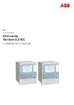
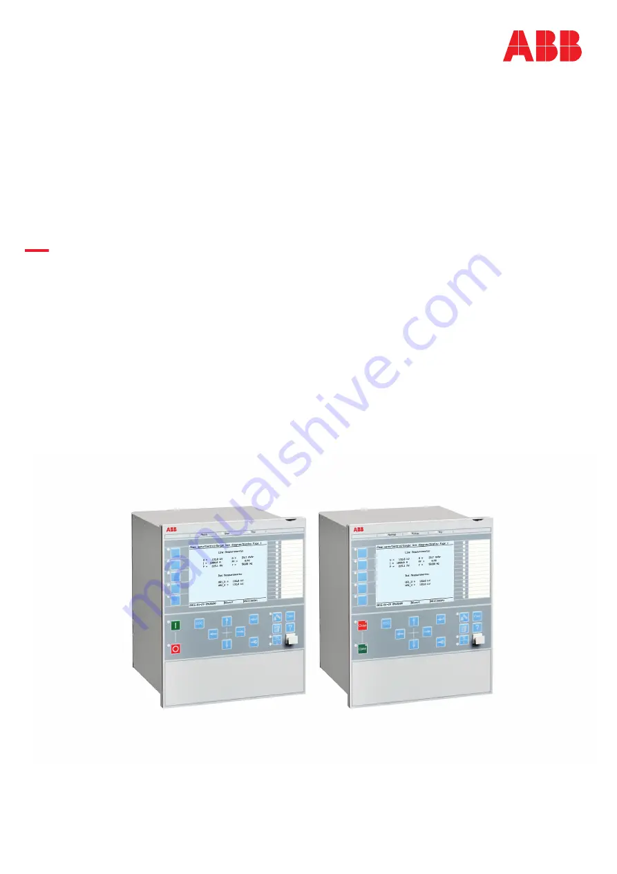
background image

Relion

®

 650 SERIES

650 series

Version 2.2 IEC

Installation manual

Summary of Contents for RELION 650 SERIES

Page 1: ...Relion 650 SERIES 650 series Version 2 2 IEC Installation manual ...

Page 2: ......

Page 3: ...Document ID 1MRK 514 027 UEN Issued May 2019 Revision D Product version 2 2 Copyright 2017 ABB All rights reserved ...

Page 4: ...erms of such license This product includes software developed by the OpenSSL Project for use in the OpenSSL Toolkit http www openssl org This product includes cryptographic software written developed by Eric Young eay cryptsoft com and Tim Hudson tjh cryptsoft com Trademarks ABB and Relion are registered trademarks of the ABB Group All other brand or product names mentioned in this document may be...

Page 5: ...y ruled out In case any errors are detected the reader is kindly requested to notify the manufacturer Other than under explicit contractual commitments in no event shall ABB be responsible or liable for any loss or damage resulting from the use of this manual or the application of the equipment ...

Page 6: ...nd concerning electrical equipment for use within specified voltage limits Low voltage directive 2006 95 EC This conformity is the result of tests conducted by ABB in accordance with the product standard EN 60255 26 for the EMC directive and with the product standards EN 60255 1 and EN 60255 27 for the low voltage directive The product is designed in accordance with the international standards of ...

Page 7: ...ing of the IED 15 Section 4 Unpacking inspecting and storing 17 4 1 Removing transport packaging 17 4 2 Inspecting the product 17 4 2 1 Identifying the product 17 4 2 2 Checking delivery items 17 4 2 3 Inspecting the IED 17 4 2 4 Returning an IED damaged in transit 17 4 3 Storing 17 Section 5 Mounting 19 5 1 Required tools 19 5 2 Checking environmental conditions and mounting space 19 5 3 Mounting...

Page 8: ...ng the binary input and output signals 37 6 1 6 Making the shield connection 39 6 2 Making of Ethernet connections 40 6 2 1 Connecting station communication interfaces 40 6 2 2 Connecting remote communication interfaces LDCM 41 6 3 Installing the serial communication cable for RS485 42 6 3 1 RS485 serial communication module 42 6 3 2 Installing the serial communication cable for RS485 SPA IEC 45 6...

Page 9: ... 53 9 1 3 Flush mounting dimensions 55 9 1 4 Side by side flush mounting dimensions 56 9 1 5 Wall mounting dimensions 57 Section 10 Glossary 59 Table of contents 650 series 3 Installation manual Copyright 2017 ABB All rights reserved ...

Page 10: ...4 ...

Page 11: ...e of such functions are HZPDIF ROTIPHIZ and STTIPHIZ 4 Parameter IBase used by the tested function is set equal to the rated CT primary current 5 Parameter UBase used by the tested function is set equal to the rated primary phase to phase voltage 6 Parameter SBase used by the tested function is set equal to 3 IBase UBase 7 The rated secondary quantities have the following values Rated secondary ph...

Page 12: ...cal and electrical installation The chapters are organized in the chronological order in which the IED should be installed The commissioning manual contains instructions on how to commission the IED The manual can also be used by system engineers and maintenance personnel for assistance during the testing phase The manual provides procedures for the checking of external circuitry and energizing th...

Page 13: ...nd product engineering for cyber security related events are described and sorted by function The guideline can be used as a technical reference during the engineering phase installation and commissioning phase and during normal service 1 3 2 Document revision history GUID BD82A13A 6FA0 4E33 BDBF 23B5A0CF968F v1 Document revision Date Product revision History 2017 05 2 2 0 First release for produc...

Page 14: ...4 169 UEN Commissioning manual 1MRK 504 171 UEN Product guide 1MRK 504 172 BEN Technical manual 1MRK 504 170 UEN Type test certificate 1MRK 504 172 TEN 650 series manuals Document numbers Operation manual 1MRK 500 128 UEN Engineering manual 1MRK 511 420 UEN Installation manual 1MRK 514 027 UEN Communication protocol manual DNP3 1MRK 511 413 UUS Communication protocol manual IEC 60870 5 103 1MRK 51...

Page 15: ...e reader of important facts and conditions The tip icon indicates advice on for example how to design your project or how to use a certain function Although warning hazards are related to personal injury it is necessary to understand that under certain operational conditions operation of damaged equipment may result in degraded process performance leading to personal injury or death It is importan...

Page 16: ...name indicates that the signal name may be customized using the PCM600 software the character after an input signal name indicates that the signal must be connected to another function block in the application configuration to achieve a valid application configuration Dimensions are provided both in inches and millimeters If it is not specifically mentioned then the dimension is in millimeters Sec...

Page 17: ...57E7 4E05 9A33 A60E359C54AF v1 Only electrically skilled persons with the proper authorization and knowledge of any safety hazards are allowed to carry out the electrical installation M2366 2 v2 National and local electrical safety regulations must always be followed Working in a high voltage environment requires serious approach to avoid human injuries and damage to equipment M2362 2 v1 Do not to...

Page 18: ...winding open will cause a massive potential build up that may damage the transformer and may cause injuries to humans M2372 2 v1 Never remove any screw from a powered IED or from a IED connected to powered circuitry Potentially lethal voltages and currents are present SEMOD168311 3 v1 Take adequate measures to protect the eyes Never look into the laser beam GUID 11CCF92B E9E7 409C 84D0 DFDEA1DCBE8...

Page 19: ...rcuitry M2698 2 v2 Take care to avoid electrical shock during installation and commissioning M2693 2 v1 Changing the active setting group will inevitably change the IEDs operation Be careful and check regulations before making the change 2 4 Note signs IP1497 1 v1 M19 2 v3 Observe the maximum allowed continuous current for the different current transformer inputs of the IED See technical data 1MRK...

Page 20: ...14 ...

Page 21: ... our products and processes 3 2 Disposing of the IED AMU0600460 v6 Definitions and regulations of hazardous materials are country specific and change when the knowledge of materials increases The materials used in this product are typical for electric and electronic devices All parts used in this product are recyclable When disposing of an IED or its parts contact a local waste handler who is auth...

Page 22: ...16 ...

Page 23: ...ments 4 2 3 Inspecting the IED GUID F6333353 F05D 4B41 BE44 5CE5274E788E v2 Check the IED to see if any damage occurred during transportation 4 2 4 Returning an IED damaged in transit GUID 966A05ED CD30 4F66 957E 00FF38943A73 v4 If damage has occurred during transport appropriate actions must be taken against the latest carrier Please inform the nearest ABB office or representative Notify ABB imme...

Page 24: ...18 ...

Page 25: ... wires and optical fibers and to enable maintenance and future modifications Ensure convection cooling around the case to minimize the heating effect within the IED Avoid installation in dusty damp places and where combustible materials are present near the IED 5 3 Mounting the IED M11978 3 v12 The IED can be rack wall or flush mounted with the use of different mounting kits see figure 2 An additi...

Page 26: ...unted in each cut out on the cubicle panel for class IP54 protection The screws from the IED shall be used to fasten the fasteners to the IED Flush mounting cannot be used for side by side mounted IEDs when IP54 class must be fulfilled Only IP20 class can be obtained when mounting two cases side by side in one 1 cut out To obtain IP54 class protection an additional factory mounted sealing must be ...

Page 27: ... rack mounting IP10313 1 v1 5 3 2 1 Overview SEMOD127656 5 v4 The IED can be mounted in a standard 19 cubicle rack by using a mounting kit consisting of two mounting angles and their fastening screws The mounting angles are reversible which enables mounting of the IED either to the left or the right side of the cubicle A separately ordered rack mounting kit for side by side mounted IEDs or IEDs to...

Page 28: ...V3 EN US Figure 4 19 panel rack mounting details The required torque for the screws is 3 5 Nm PosNo Description Quantity Type 1a 1b Mounting angles can be mounted either to the left or the right side of the case 2 2 Screw 8 M4x6 3 Washer 8 M4x6 5 3 3 Wall mounting IP10316 1 v1 5 3 3 1 Overview M11973 3 v7 The IED can be mounted on a wall a panel or in a cubicle Section 5 1MRK 514 027 UEN D Mountin...

Page 29: ...ing details 5 3 3 3 How to reach the rear side of the IED M11941 2 v5 The IED can be equipped with a rear protection cover recommended to be used with this type of mounting See figure 6 To reach the rear side of the IED a free space of 80 mm is required on the unhinged side 80 mm 1 3 2 IEC06000135 2 en vsd IEC06000135 V3 EN US Figure 6 How to reach the connectors on the rear side of the IED PosNo ...

Page 30: ...procedure for side by side rack mounting M11955 2 v4 IEC040004563enOriginal vsdx 1 2 3 4 3 IEC04000456 V3 EN US Figure 7 Side by side rack mounting details The required torque for the screws is 3 5 Nm PosNo Description Quantity Type 1 Mounting plate 2 2 3 Screw 16 M4x6 4 Mounting angle 2 5 Washer 16 M4x6 5 3 4 3 IED mounted with a RHGS6 case M11953 3 v4 A 1 2 x 19 size IED can be mounted with a RH...

Page 31: ...nting kit must be used The mounting kit has to be ordered separately The maximum size of the panel cut out is 19 With side by side flush mounting installation only IP class 20 is obtained To reach IP class 54 it is required to mount the IEDs separately For cut out dimensions of separately mounted IEDs see section Flush mounting Use only the screws included in the mounting kit when mounting the pla...

Page 32: ...e 9 Side by side flush mounting details RHGS6 side by side with 1 2 x 19 IED The required torque for the screws is 3 5 Nm PosNo Description Quantity Type 1 Mounting plate 2 2 3 Screw washer 16 M4x6 4 Mounting angle 2 Section 5 1MRK 514 027 UEN D Mounting 26 650 series Installation manual Copyright 2017 ABB All rights reserved ...

Page 33: ...parates the internal circuits from the VT and CT circuits It has 12 analog inputs Analog digital conversion module ADM The module converts the VT and CT analog signals from the TRM to digital signals processed by the NUM Carrier for communication boards Note TRM module is not included in SAM600 IO so ADM module is only used for internal communication carrier for IO modules Combined backplane modul...

Page 34: ...ication module RS485 Module used for DNP3 and IEC 60870 5 103 communication IRIG B Time synchronization module IRIG B Module with 2 inputs One is used for handling both pulse width modulated signals and amplitude modulated signals and one is used for optical input type ST for PPS time synchronization 6 1 1 2 Front side connectors SEMOD129384 5 v3 IEC16000051 V1 EN US Figure 11 RJ 45 communication ...

Page 35: ...view X11 X31 X41 X51 X401 X301 X302 X303 X304 X311 A B C D X305 X312 X306 X313 X32 X42 X52 6U IEC17000067 V1 EN US Rear position Module X11 PSM X31 and X32 etc to X51 and X52 BIM BOM or IOM X301 X302 X303 X304 SFP X305 LDCM X306 LDCM X311 A B C D SLM X312 LDCM or IRIG B X313 LDCM IRIG B or RS485 X401 TRM 1MRK 514 027 UEN D Section 6 Connecting 650 series 29 Installation manual Copyright 2017 ABB A...

Page 36: ... 110 220V 9I 3U 5A 5A 5A 5A 5A 5A 5A 5A 5A 5A 110 220V 110 220V 110 220V 7I 5U 1A 1A 1A 1A 1A 1A 1A 1A 110 220V 110 220V 110 220V 110 220V 110 220V 7I 5U 5A 5A 5A 5A 5A 5A 5A 5A 110 220V 110 220V 110 220V 110 220V 110 220V 6I 5A 1I 1A 5U 5A 5A 5A 5A 5A 5A 1A 110 220V 110 220V 110 220V 110 220V 110 220V 3I 5A 4I 1A 5U 5A 5A 5A 1A 1A 1A 1A 110 220V 110 220V 110 220V 110 220V 110 220V Note that inter...

Page 37: ...Binary input module BIM 1MRK006501 AF INTERFACES IEC 6502P1 V1 EN US Figure 14 IED with basic functionality and communication interfaces 1MRK 514 027 UEN D Section 6 Connecting 650 series 31 Installation manual Copyright 2017 ABB All rights reserved ...

Page 38: ...ve earth must be connected EL 1MRK002801 AC 7 670 1 2 PG V3 EN US Figure 15 Power supply module PSM 1MRK002801 AC 12 670 1 2 PG V1 EN US Figure 16 Binary output module BOM Section 6 1MRK 514 027 UEN D Connecting 32 650 series Installation manual Copyright 2017 ABB All rights reserved ...

Page 39: ...maintenance The plate with resistors should be provided with a protective cover mounted in a separate box or in a locked cubicle National law and standards shall be followed Connections for three phase high impedance differential protection GUID C12CCAAF 5AE5 4A9C AC9C F56A66FD2C14 v8 Generator reactor or busbar differential protection is a typical application for three phase high impedance differ...

Page 40: ...4 mm screw terminal on the plate 3 Necessary connection for three phase metrosil set 4 Position of optional test switch for secondary injection into the high impedance differential IED 5 Necessary connection for setting resistors 6 Factory made star point on a three phase setting resistor set The star point connector must be removed for installations with 650 series IEDs This star point is require...

Page 41: ...ssary connection for the metrosil 4 Position of optional test switch for secondary injection into the high impedance differential IED 5 Necessary connection for stabilizing resistor 6 How to connect the high impedance restricted earth fault protection scheme to one CT input in IED 6 1 2 Connecting to protective earth M11997 4 v11 Connect the protective earthing screw pos 1 in figure 20 on the rear...

Page 42: ... circuit board and the external wiring connected to the screw terminal block The auxiliary power wiring should have a minimum cross sectional area of 1 0 mm2 and a voltage rating of 250 V Branch circuit protection must be provided in the auxiliary power supply wiring to the IED and if necessary it must be possible to disconnect manually from the power supply Fuse or circuit breaker up to 6 A and 2...

Page 43: ...ation of BIM BOM and IOM refer to section Rear side connectors Connection diagrams for BIM BOM and IOM are shown in Figure 13 Figure 16 and Figure 17 Do not insert anything else to the female connector but the corresponding male connector Inserting anything else such as a measurement probe may violate the female connector and prevent a proper electrical contact between the printed circuit board an...

Page 44: ...IEC16000050 V1 EN US Figure 21 A female connector top screw compression type bottom ringlug type IEC04000167 V1 EN US Figure 22 Board with male connectors Section 6 1MRK 514 027 UEN D Connecting 38 650 series Installation manual Copyright 2017 ABB All rights reserved ...

Page 45: ...x AWG18 Terminal blocks suitable for ring lug terminals 300 V AC 3 mm2 AWG14 Table 7 Binary I O connectors Connector type Rated voltage Maximum conductor area Screw compression type 250 V AC 2 5 mm2 AWG14 2 1 mm2 2 x AWG18 6 1 6 Making the shield connection M11998 3 v6 When using shielded cables always make sure that the shields are connected according to applicable engineering methods 1MRK 514 02...

Page 46: ...one basic and three optional These ports are used for IEC 61850 or DNP3 communication The serial communication module SLM provides four optical ports which are used for LON SPA IEC 60870 5 103 or DNP3 communication Ports X301 to X304 on the NUM module are used for IEC 61850 8 1 and IEC UCA 61850 9 2LE communication Ports X301 X302 and X303 X304 are to be used in pairs for redundant communication T...

Page 47: ... that the LAN cables are mounted and fixed with sufficient distance to all HLV circuits During transportation of a relay mounted in a cubicle the optical fibers must be disconnected from the OEM ports Strictly follow the instructions from the manufacturer for specific types of optical cables connectors When utilizing galvanic RJ45 SFP ports for the IEDs network connection s the installation shall ...

Page 48: ...eiver connect to RX x1 5 reserved RX Receive low x1 6 reserved RX Receive high 2 wire Connect pin X1 1 to pin X1 6 and pin X1 2 to pin X1 5 Termination 2 wire Connect pin X1 1 to pin X1 3 Termination 4 wire Connect pin X1 1 to pin X1 3 and pin X1 4 to pin X1 6 The distance between connection points should be 1200 m 3000 ft see Figures 26 and 27 Only the outer shielding is connected to the IED with...

Page 49: ...ation cable installation 2 wire Where 1 The inner shields shall be connected together with an isolated terminal block and only have one connection point in the whole system preferably at the external equipment PC The outer shield shall be connected to the IED chassis in every cable end Use the shield connection clamp at all IEDs The first IED will have only one cable end but all others require two...

Page 50: ... cable end Use the shield connection clamp at all IEDs The first IED will have only one cable end but all others require two 2 Connect according to installation instructions for the actual equipment observe the 120 ohms termination 3 Connect the screens according to the installation instructions for the actual equipment 4 Shield connection clamp see Figure 24 Cc Communication cable en03000110 vsd ...

Page 51: ...ms 2 Transmission method RS 485 differential bipolar signaling 2 1 Differential signal levels Two differential signal levels are defined A line A positive with respect to line B A line A negative with respect to line B 2 2 Galvanic isolation The RS485 circuit shall be isolated from earth by Riso 10 MW Ciso 10 pF Three isolation options exist a The entire node electronics can be galvanically isolat...

Page 52: ...al A 220 W 0 25 W 2 5 c Rd Signal A to GND 390 W 0 25 W 2 5 2 3 3 Bus power distribution The end node in each Ph segment applies 5 V bus excitation power to the Termination network via the Excitation pair ExV and GND used in the Type 3 Physical layer specification 6 3 3 Data on RS485 serial communication module cable SEMOD176342 280 v2 Type Twisted pair S STP Screened Screened Twisted Pair Shield ...

Page 53: ... auxiliary supply voltage remains within the permissible input voltage range under all operating conditions Check that the polarity is correct before energizing the IED 7 4 Energizing the IED GUID E40DE80C 8DA4 4E17 876C 4CC3CE706347 v4 Before connecting the auxiliary power check that the terminal strip is wired and placed correctly Remove the protective film from the top side of the unit During I...

Page 54: ...48 ...

Page 55: ...ct related information including product type serial number order number production date and SW version The Installed HW submenu contains information about the HW modules 8 3 Removing the IED GUID 6F99E661 D319 4782 97E9 3A864B1E972D v2 Before removing the IED make sure that auxiliary power is turned off and all wiring is disconnected For upgrade purposes the IED does not need to be removed Before...

Page 56: ...50 ...

Page 57: ...1 Case without protective cover SEMOD53195 1 v2 M2152 3 v8 IEC08000164 4 en vsdx IEC08000164 V4 EN US Figure 31 Case without protective cover 1MRK 514 027 UEN D Section 9 Technical data 650 series 51 Installation manual Copyright 2017 ABB All rights reserved ...

Page 58: ...unting kit M2152 11 v5 Case size mm A B C D E F G H I 6U 1 2 x 19 265 9 223 7 204 1 249 9 205 8 190 5 466 5 189 1 482 6 The G and I dimensions are defined by the 19 rack mounting kit Section 9 1MRK 514 027 UEN D Technical data 52 650 series Installation manual Copyright 2017 ABB All rights reserved ...

Page 59: ...ver SEMOD53199 1 v2 M11985 110 v7 IEC08000163 3 en vsdx IEC08000163 V3 EN US Figure 33 Case with protective cover 1MRK 514 027 UEN D Section 9 Technical data 650 series 53 Installation manual Copyright 2017 ABB All rights reserved ...

Page 60: ...5 3 en vsdx IEC08000165 V3 EN US Figure 34 Case with protective cover and 19 rack mounting kit Section 9 1MRK 514 027 UEN D Technical data 54 650 series Installation manual Copyright 2017 ABB All rights reserved ...

Page 61: ...9 223 7 247 5 255 0 205 8 190 5 466 5 232 5 482 6 The G and I dimensions are defined by the 19 rack mounting kit 9 1 3 Flush mounting dimensions M11571 3 v6 C A IEC04000465 3 en vsd B E D IEC04000465 V3 EN US Figure 36 Flush mounting 1MRK 514 027 UEN D Section 9 Technical data 650 series 55 Installation manual Copyright 2017 ABB All rights reserved ...

Page 62: ...6000182 2 en vsd IEC06000182 V2 EN US Figure 37 A 1 2 x 19 size IED side by side with RHGS6 xx05000505 vsd B A C G D E F IEC05000505 V1 EN US Figure 38 Panel cut out dimensions for side by side flush mounting Case size mm Tolerance A 1 B 1 C 1 D 1 E 1 F 1 G 1 6U 1 2 x 19 214 0 259 3 240 4 190 5 34 4 13 2 6 4 diam Section 9 1MRK 514 027 UEN D Technical data 56 650 series Installation manual Copyrig...

Page 63: ...EC04000471 2 en vsd IEC04000471 V2 EN US Figure 39 Wall mounting Case size mm A B C D E 6U 1 2 x 19 292 0 267 1 272 8 390 0 243 0 1MRK 514 027 UEN D Section 9 Technical data 650 series 57 Installation manual Copyright 2017 ABB All rights reserved ...

Page 64: ...58 ...

Page 65: ...ry outputs status BR External bistable relay BS British Standards BSR Binary signal transfer function receiver blocks BST Binary signal transfer function transmit blocks C37 94 IEEE ANSI protocol used when sending binary signals between IEDs CAN Controller Area Network ISO standard ISO 11898 for serial communication CB Circuit breaker CBM Combined backplane module CCITT Consultative Committee for ...

Page 66: ... unit CVT or CCVT Capacitive voltage transformer DAR Delayed autoreclosing DARPA Defense Advanced Research Projects Agency The US developer of the TCP IP protocol etc DBDL Dead bus dead line DBLL Dead bus live line DC Direct current DFC Data flow control DFT Discrete Fourier transform DHCP Dynamic Host Configuration Protocol DIP switch Small switch mounted on a printed circuit board DI Digital inp...

Page 67: ...Gas insulated switchgear GOOSE Generic object oriented substation event GPS Global positioning system GSAL Generic security application GSE Generic substation event HDLC protocol High level data link control protocol based on the HDLC standard HFBR connector type Plastic fiber connector HLV circuit Hazardous Live Voltage according to IEC60255 27 HMI Human machine interface HSAR High speed autorecl...

Page 68: ... of a function in the IED is representative of a type of function IP 1 Internet protocol The network layer for the TCP IP protocol suite widely used on Ethernet networks IP is a connectionless best effort packet switching protocol It provides packet routing fragmentation and reassembly through the data link layer 2 Ingression protection according to IEC 60529 IP 20 Ingression protection according ...

Page 69: ...e card POR Permissive overreach POTT Permissive overreach transfer trip Process bus Bus or LAN used at the process level that is in near proximity to the measured and or controlled components PRP Parallel redundancy protocol PSM Power supply module PST Parameter setting tool within PCM600 PTP Precision time protocol PT ratio Potential transformer or voltage transformer ratio PUTT Permissive underr...

Page 70: ...r generator SVC Static VAr compensation TC Trip coil TCS Trip circuit supervision TCP Transmission control protocol The most common transport layer protocol used on Ethernet and the Internet TCP IP Transmission control protocol over Internet Protocol The de facto standard Ethernet protocols incorporated into 4 2BSD Unix TCP IP was developed by DARPA for Internet working and encompasses both networ...

Page 71: ...seconds to synchronize it with Universal Time 1 UT1 thus allowing for the eccentricity of the Earth s orbit the rotational axis tilt 23 5 degrees but still showing the Earth s irregular rotation on which UT1 is based The Coordinated Universal Time is expressed using a 24 hour clock and uses the Gregorian calendar It is used for aeroplane and ship navigation where it is also sometimes known by the ...

Page 72: ...66 ...

Page 73: ...67 ...

Page 74: ...B AB Grid Automation Products SE 721 59 Västerås Sweden Phone 46 0 21 32 50 00 www abb com protection control Copyright 2017 ABB All rights reserved Scan this QR code to visit our website 1MRK 514 027 UEN ...

Reviews: