


The different network configuration classes are:
1. Parallel line with common positive and zero sequence network
2. Parallel circuits with common positive but separated zero sequence network
3. Parallel circuits with positive and zero sequence sources separated.
One example of class 3 networks could be the mutual coupling between a 400 kV line
and rail road overhead lines. This type of mutual coupling is not so common although
it exists and is not treated any further in this manual.
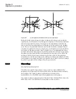
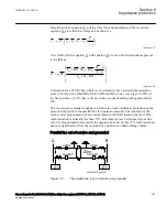
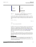
For each type of network class, there are three different topologies; the parallel line can
be in service, out of service, out of service and grounded in both ends.
The reach of the distance protection zone 1 will be different depending on the
operation condition of the parallel line. This can be handled by the use of different
setting groups for handling the cases when the parallel line is in operation and out of
service and grounded at both ends.
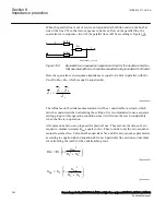
The distance protection within the IED can compensate for the influence of a zero
sequence mutual coupling on the measurement at single phase-to-ground faults in the
following ways, by using:
•
The possibility of different setting values that influence the ground-return
compensation for different distance zones within the same group of setting
parameters.
•
Different groups of setting parameters for different operating conditions of a
protected multi circuit line.
Most multi circuit lines have two parallel operating circuits.
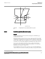
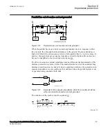
Parallel line applications
GUID-74355B21-61D3-47A9-A3AE-2D56B2EDDC3C v1
This type of networks is defined as those networks where the parallel transmission
lines terminate at common nodes at both ends.
The three most common operation modes are:
1. Parallel line in service.
2. Parallel line out of service and grounded.
3. Parallel line out of service and not grounded.
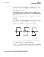
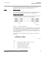
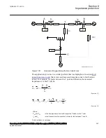
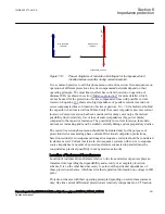
Parallel line in service
GUID-0C0B1323-C69D-4EFE-A3CF-C81D762ED146 v2
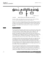
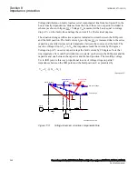
This type of application is very common and applies to all normal sub-transmission
and transmission networks.
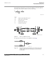
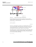
Let us analyze what happens when a fault occurs on the parallel line see figure
.
Section 8
1MRK 502 071-UUS A
Impedance protection
236
Generator protection REG670 2.2 ANSI and Injection equipment REX060, REX061, REX062
Application manual
Summary of Contents for RELION 670 SERIES REG670
Page 1: ...RELION 670 SERIES Generator protection REG670 Version 2 2 ANSI Application manual ...
Page 2: ......
Page 44: ...38 ...
Page 66: ...60 ...
Page 102: ...96 ...
Page 200: ...194 ...
Page 442: ...436 ...
Page 486: ...480 ...
Page 508: ...502 ...
Page 514: ...508 ...
Page 524: ...518 ...
Page 658: ...652 ...
Page 736: ...730 ...
Page 774: ...768 ...
Page 828: ...822 ...
Page 829: ...823 ...


