


blocks distance protection. Another method employed is to temporarily block the
signals received at the healthy line as soon as the parallel faulty line protection initiates
tripping. The second mentioned method has an advantage in that not the whole
protection is blocked for the short period. The disadvantage is that a local
communication is needed between two protection devices in the neighboring bays of
the same substation.
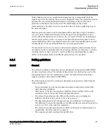
Distance protection used on series compensated lines must have a high overreach to
cover the whole transmission line also when the capacitors are bypassed or out of
service. When the capacitors are in service, the overreach will increase tremendously
and the whole system will be very sensitive for false teleprotection signals. Current
reversal difficulties will be accentuated because the ratio of mutual impedance against
self-impedance will be much higher than for a non-compensated line.
If non-unit protection is to be used in a directional comparison mode, schemes based
on negative sequence quantities offer the advantage that they are insensitive to mutual
coupling. However, they can only be used for phase-to-ground and phase-to-phase
faults. For three-phase faults an additional protection must be provided.
8.3.4
Setting guidelines
IP14962-1 v1
8.3.4.1
General
GUID-B9958CEF-90ED-4644-B169-C6B4A018193B v1
The settings for Distance measuring zones, quadrilateral characteristic (ZMFCPDIS)
are done in primary values. The instrument transformer ratio that has been set for the
analog input card is used to automatically convert the measured secondary input
signals to primary values used in ZMFCPDIS.
The following basics must be considered, depending on application, when doing the
setting calculations:
•
Errors introduced by current and voltage instrument transformers, particularly
under transient conditions.
•
Inaccuracies in the line zero-sequence impedance data, and their effect on the
calculated value of the ground-return compensation factor.
•
The effect of infeed between the IED and the fault location, including the
influence of different Z
0
/Z
1
ratios of the various sources.
•
The phase impedance of non transposed lines is not identical for all fault loops.
The difference between the impedances for different phase-to-ground loops can be
as large as 5-10% of the total line impedance.
•
The effect of a load transfer between the IEDs of the protected fault resistance is
considerable, the effect must be recognized.
•
Zero-sequence mutual coupling from parallel lines.
1MRK 502 071-UUS A
Section 8
Impedance protection
Generator protection REG670 2.2 ANSI and Injection equipment REX060, REX061, REX062
265
Application manual
Summary of Contents for RELION 670 SERIES REG670
Page 1: ...RELION 670 SERIES Generator protection REG670 Version 2 2 ANSI Application manual ...
Page 2: ......
Page 44: ...38 ...
Page 66: ...60 ...
Page 102: ...96 ...
Page 200: ...194 ...
Page 442: ...436 ...
Page 486: ...480 ...
Page 508: ...502 ...
Page 514: ...508 ...
Page 524: ...518 ...
Page 658: ...652 ...
Page 736: ...730 ...
Page 774: ...768 ...
Page 828: ...822 ...
Page 829: ...823 ...


