Z0m
A
B
21
21
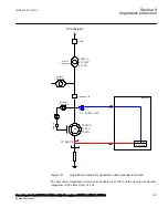
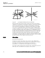
en05000221_ansi.vsd
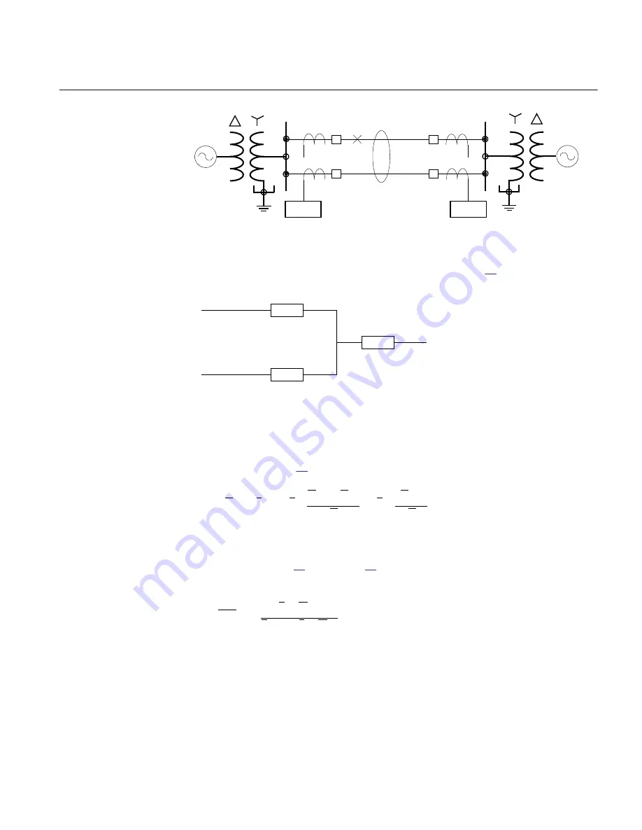
FAULT
ANSI05000221 V1 EN-US
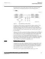
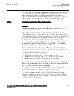
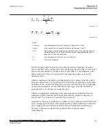
Figure 84:
Class 1, parallel line in service
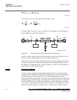
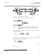
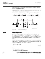
The equivalent circuit of the lines can be simplified, see figure
A
B
C
Z
0m
Z
0m
Z
0
-
Z
0m
Z
0
-
IEC09000253_1_en.vsd
IEC09000253 V1 EN-US
Figure 85:
Equivalent zero sequence impedance circuit of the double-circuit,
parallel, operating line with a single phase-to-ground fault at the
remote busbar
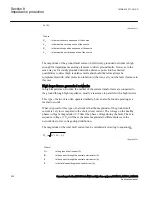
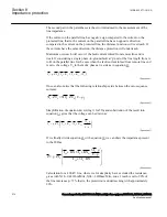
When mutual coupling is introduced, the voltage at the relay point A will be changed
according to equation
0
0
0
0
1
1
3
3
3 1
3 1
m
L
L
ph
p
ph
L
L
L
Z
Z
Z
V
Z
I
I
I
Z
Z
æ
ö
-
=
×
+
×
+
ç
÷
×
×
è
ø
EQUATION1276 V4 EN-US
(Equation 39)
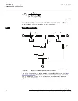
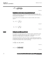
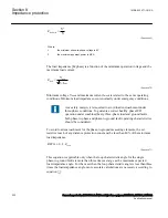
By dividing equation
and after some simplification we can write the
impedance present to the relay at A side as:
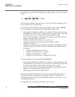
3 0
1 1
3 0
æ
ö
×
=
+
ç
÷
+
×
è
ø
L
I
KNm
Z
Z
I ph
I
KN
EQUATION1277 V3 EN-US
(Equation 40)
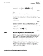
Where:
KNm
= Z0m/(3 · Z1L)
1MRK 502 071-UUS A
Section 8
Impedance protection
Generator protection REG670 2.2 ANSI and Injection equipment REX060, REX061, REX062
209
Application manual
Summary of Contents for RELION 670 SERIES REG670
Page 1: ...RELION 670 SERIES Generator protection REG670 Version 2 2 ANSI Application manual ...
Page 2: ......
Page 44: ...38 ...
Page 66: ...60 ...
Page 102: ...96 ...
Page 200: ...194 ...
Page 442: ...436 ...
Page 486: ...480 ...
Page 508: ...502 ...
Page 514: ...508 ...
Page 524: ...518 ...
Page 658: ...652 ...
Page 736: ...730 ...
Page 774: ...768 ...
Page 828: ...822 ...
Page 829: ...823 ...


