background image


RELION® 670 SERIES

— 

670 series 

Version 2.2 IEC 

Installation manual

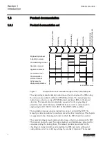
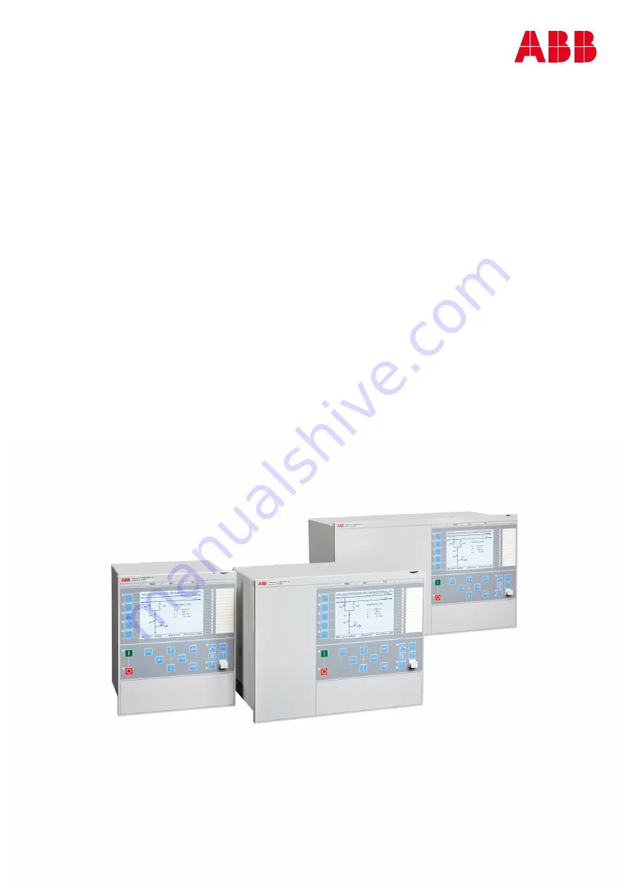
Summary of Contents for Relion 670 series

Page 1: ...RELION 670 SERIES 670 series Version 2 2 IEC Installation manual ...

Page 2: ......

Page 3: ...Document ID 1MRK 514 026 UEN Issued October 2017 Revision B Product version 2 2 1 Copyright 2017 ABB All rights reserved ...

Page 4: ...erms of such license This product includes software developed by the OpenSSL Project for use in the OpenSSL Toolkit http www openssl org This product includes cryptographic software written developed by Eric Young eay cryptsoft com and Tim Hudson tjh cryptsoft com Trademarks ABB and Relion are registered trademarks of the ABB Group All other brand or product names mentioned in this document may be...

Page 5: ...y ruled out In case any errors are detected the reader is kindly requested to notify the manufacturer Other than under explicit contractual commitments in no event shall ABB be responsible or liable for any loss or damage resulting from the use of this manual or the application of the equipment ...

Page 6: ...nd concerning electrical equipment for use within specified voltage limits Low voltage directive 2006 95 EC This conformity is the result of tests conducted by ABB in accordance with the product standard EN 60255 26 for the EMC directive and with the product standards EN 60255 1 and EN 60255 27 for the low voltage directive The product is designed in accordance with the international standards of ...

Page 7: ...velopment 17 Disposing of the IED 17 Section 4 Unpacking inspecting and storing 19 Removing transport packaging 19 Inspecting the product 19 Identifying the product 19 Checking delivery items 19 Inspecting the IED 19 Returning an IED damaged in transit 20 Storing 20 Section 5 Mounting 21 Required tools 21 Checking environmental conditions and mounting space 21 Mounting the IED 21 Flush mounting 22...

Page 8: ...for high impedance differential protection 49 Connecting to protective earth 51 Connecting the power supply module 52 Connecting to CT and VT circuits 52 Connecting the binary input and output signals 53 Making the shield connection 55 Making the electrical connection to the rotor and stator injection equipment REG670 only 57 Connectors for injection unit REX060 coupling capacitor unit REX061 and ...

Page 9: ... version 83 Checking mounting 83 Checking the power supply 83 Energizing the IED 83 Section 8 Removing repairing and exchanging 85 Product lifecycle 85 Checking IED information 85 Removing the IED 85 Sending the IED for repair 86 Exchanging the IED 86 Section 9 Technical data 87 Dimensions 87 Case without rear cover 87 Case with rear cover 89 Flush mounting dimensions 91 Side by side flush mountin...

Page 10: ...4 ...

Page 11: ...stallation The chapters are organized in the chronological order in which the IED should be installed 1 2 Intended audience GUID C9B8127F 5748 4BEA 9E4F CC762FE28A3A v11 This manual addresses the personnel responsible for installing the product hardware The installation personnel must have basic knowledge of handling electronic equipment 1MRK 514 026 UEN B Section 1 Introduction 670 series 2 2 IEC...

Page 12: ...EDs to the project structure The manual also recommends a sequence for the engineering of protection and control functions LHMI functions as well as communication engineering for IEC 60870 5 103 IEC 61850 DNP3 LON and SPA The installation manual contains instructions on how to install the IED The manual provides procedures for mechanical and electrical installation The chapters are organized in th...

Page 13: ...signals setting parameters and technical data sorted per function The manual can be used as a technical reference during the engineering phase installation and commissioning phase and during normal service The communication protocol manual describes the communication protocols supported by the IED The manual concentrates on the vendor specific implementations The point list manual describes the ou...

Page 14: ... to RED670 Document numbers Application manual 1MRK 505 376 UEN Commissioning manual 1MRK 505 378 UEN Product guide 1MRK 505 379 BEN Technical manual 1MRK 505 377 UEN Type test certificate 1MRK 505 379 TEN Documents related to REG670 Document numbers Application manual 1MRK 502 071 UEN Commissioning manual 1MRK 502 073 UEN Product guide 1MRK 502 074 BEN Technical manual 1MRK 502 072 UEN Type test ...

Page 15: ...378 TEN 670 series manuals Document numbers Operation manual 1MRK 500 127 UEN Engineering manual 1MRK 511 398 UEN Installation manual 1MRK 514 026 UEN Communication protocol manual DNP3 1MRK 511 391 UUS Communication protocol manual IEC 60870 5 103 1MRK 511 394 UEN Communication protocol manual IEC 61850 Edition 1 1MRK 511 392 UEN Communication protocol manual IEC 61850 Edition 2 1MRK 511 393 UEN ...

Page 16: ...ons The tip icon indicates advice on for example how to design your project or how to use a certain function Although warning hazards are related to personal injury it is necessary to understand that under certain operational conditions operation of damaged equipment may result in degraded process performance leading to personal injury or death It is important that the user fully complies with all...

Page 17: ... configuration to achieve a valid application configuration Logic diagrams describe the signal logic inside the function block and are bordered by dashed lines Signals in frames with a shaded area on their right hand side represent setting parameter signals that are only settable via the PST ECT or LHMI If an internal signal path cannot be drawn with a continuous line the suffix int is added to th...

Page 18: ...12 ...

Page 19: ...rnings IP1504 1 v2 Observe the warnings during all types of work related to the product GUID C9B6638A 57E7 4E05 9A33 A60E359C54AF v1 Only electrically skilled persons with the proper authorization and knowledge of any safety hazards are allowed to carry out the electrical installation M2366 2 v2 National and local electrical safety regulations must always be followed Working in a high voltage envi...

Page 20: ... site configuration This is class 1 equipment that shall be earthed M2367 2 v1 Never disconnect the secondary connection of current transformer circuit without short circuiting the transformer s secondary winding Operating a current transformer with the secondary winding open will cause a massive potential build up that may damage the transformer and may cause injuries to humans M2372 2 v1 Never r...

Page 21: ...uctive wrist strap connected to protective earth when replacing modules Electrostatic discharge ESD may damage the module and IED circuitry M2698 2 v2 Take care to avoid electrical shock during installation and commissioning M2693 2 v1 Changing the active setting group will inevitably change the IEDs operation Be careful and check regulations before making the change GUID 3BEE51C6 8793 4C89 B8A8 0...

Page 22: ... v1 M19 2 v3 Observe the maximum allowed continuous current for the different current transformer inputs of the IED See technical data Section 2 1MRK 514 026 UEN B Safety information 16 670 series 2 2 IEC Installation manual ...

Page 23: ...te their effect on our products and processes 3 2 Disposing of the IED AMU0600460 v6 Definitions and regulations of hazardous materials are country specific and change when the knowledge of materials increases The materials used in this product are typical for electric and electronic devices All parts used in this product are recyclable When disposing of an IED or its parts contact a local waste h...

Page 24: ...18 ...

Page 25: ...s order number with the ordering information to verify that the received product is correct 4 2 2 Checking delivery items GUID 2A6D8F5A 470F 40D1 9EAE 60DE4DD85EE6 v1 Check that all items are included in the delivery in accordance with the delivery documents 4 2 3 Inspecting the IED GUID F6333353 F05D 4B41 BE44 5CE5274E788E v1 IEDs require careful handling before installation on site Check the IED...

Page 26: ...discrepancies in relation to the delivery documents 4 3 Storing GUID 1DC9D33D DC62 438B 9333 3BB354164CBC v7 Storing of the IED before installation must be done in the original transport packaging in a dry and dust free place Storage temperature must be within the range of 40 C to 70 C The average high temperature is recommended to be less than 40 C to minimize component ageing Section 4 1MRK 514 ...

Page 27: ... normal environment Avoid installation in dusty damp areas Check that sufficient space is available Sufficient space is needed at the front and rear of the IED to allow access to wires and optical fibres and to enable maintenance and future modifications Ensure convection cooling around the case to minimize the heating effect within the IED Avoid installation in dusty damp places and where combust...

Page 28: ...oduct guide They are also available for ordering in the Accessories guide A B C D IEC06000147 4 en vsdx IEC06000147 V4 EN US Figure 2 Different mounting methods Description A Flush mounting B 19 Panel rack mounting C Wall mounting D Side by side rack or flush mounting 5 3 1 Flush mounting IP10303 1 v1 5 3 1 1 Overview M11967 3 v5 The flush mounting kit can be used for case sizes Section 5 1MRK 514...

Page 29: ...mounted IEDs when IP54 class must be fulfilled Only IP20 class can be obtained when mounting two cases side by side in one 1 cut out To obtain IP54 class protection an additional factory mounted sealing must be ordered when ordering the IED 5 3 1 2 Mounting procedure for flush mounting M11942 2 v5 1 5 6 3 IEC16000080 1 en vsd 2 4 IEC16000080 V1 EN US Figure 3 Flush mounting details 1MRK 514 026 UE...

Page 30: ...isting of two mounting angles their fastening screws and washers The mounting angles are reversible which enables mounting of IED size 1 2 x 19 or 3 4 x 19 either to the left or the right side of the cubicle A separately ordered rack mounting kit for side by side mounted IEDs or IEDs together with RHGS cases should be selected so that the total size equals 19 Use only the screws included in the mo...

Page 31: ...ack mounting M11948 2 v6 1a IEC08000160 3 en vsdx 1a 2 3 IEC08000160 V3 EN US Figure 4 19 panel rack mounting details The required torque for the screws is 3 5 Nm 1MRK 514 026 UEN B Section 5 Mounting 670 series 2 2 IEC 25 Installation manual ...

Page 32: ...ounted It is also possible to mount the IED on a panel or in a cubicle Use only the screws included in the mounting kit when mounting the plates and the angles on the IED Screws with wrong dimension may damage the PCBs inside the IED If fiber cables are bent too much the signal can be weakened Wall mounting is therefore not recommended for any communication modules with fiber connection Section 5 ...

Page 33: ... M6x12 or corresponding 4 Mounting bar 2 5 Screw 6 M5x8 6 Side plate 2 5 3 3 3 How to reach the rear side of the IED M11941 2 v5 The IED can be equipped with a rear protection cover recommended to be used with this type of mounting See figure 6 To reach the rear side of the IED a free space of 80 mm is required on the unhinged side 1MRK 514 026 UEN B Section 5 Mounting 670 series 2 2 IEC 27 Instal...

Page 34: ...ize 1 2 x 19 or 3 4 x 19 and RHGS cases can be mounted side by side up to a maximum size of 19 For side by side rack mounting the side by side mounting kit together with the 19 rack panel mounting kit must be used The mounting kit has to be ordered separately Use only the screws included in the mounting kit when mounting the plates and the angles on the IED Screws with wrong dimension may damage t...

Page 35: ... 2 3 Screw 16 M4x6 4 Mounting angle 2 5 Washer 16 M4x6 5 3 4 3 IED mounted with a RHGS6 case M11953 3 v4 A 1 2 x 19 or 3 4 x 19 size IED can be mounted with a RHGS case 6 or 12 depending on IED size The RHGS case can be used for mounting a test switch of type RTXP 24 It also has enough space for a terminal base of RX 2 type for mounting of for example a DC switch or two auxiliary relays 1MRK 514 0...

Page 36: ... panel rack mounting kit must be used The mounting kit has to be ordered separately The maximum size of the panel cut out is 19 With side by side flush mounting installation only IP class 20 is obtained To reach IP class 54 it is required to mount the IEDs separately For cut out dimensions of separately mounted IEDs see section Flush mounting Use only the screws included in the mounting kit when m...

Page 37: ...x6 4 Mounting angle 2 5 3 6 Mounting the injection unit REX060 REG670 only GUID 264732AC 6C84 44E6 9F86 2065AD0B7D5B v3 The injection unit REX060 case size is 6U 1 2 x 19 REX060 can be rack wall or flush mounted in the same way as the IED For guidance see instructions for rack mounting wall mounting or flush mounting the IED in this manual REX060 shall be mounted close to the IED It is recommended...

Page 38: ...8DEA 209F77CA5173 v5 X1 X2 IEC11000019 2 en vsd IEC11000019 V1 EN US Figure 10 Coupling capacitor unit REX061 217 8 54 255 10 235 9 25 84 3 3 84 3 3 Ø 5 5 0 22 223 8 78 2 0 079 155 6 1 199 7 83 38 1 5 IEC11000037 2 en vsd IEC11000037 V2 EN US Figure 11 Measure and drilling plan Section 5 1MRK 514 026 UEN B Mounting 32 670 series 2 2 IEC Installation manual ...

Page 39: ...o heat dissipation up to about 50 C above the ambient temperature It must be installed to get a open air convection and prevent contact with combustible material to the surface 5 3 7 2 Shunt resistor unit REX062 GUID 184D9033 33F3 4F85 8847 E9FDC95C3C41 v5 X1 IEC11000038 1 en vsd IEC11000038 V1 EN US Figure 12 Shunt resistor unit REX062 1MRK 514 026 UEN B Section 5 Mounting 670 series 2 2 IEC 33 I...

Page 40: ...o the IED It is recommended that REX060 and REX062 are mounted in the same cubicle as the IED The surface of REX062 unit may be temporarily very hot due to heat dissipation up to about 65 C above the ambient temperature It must be installed to get a open air convection and prevent contact with combustible material to the surface Section 5 1MRK 514 026 UEN B Mounting 34 670 series 2 2 IEC Installat...

Page 41: ...The module provides four SFPs for Ethernet traffic Local Human machine interface LHMI The module consists of LEDs an LCD a push button keyboard and an ethernet connector used to connect a PC to the IED Transformer input module TRM Transformer module that galvanically separates the internal circuits from the VT and CT circuits It has 12 analog inputs Analog digital conversion module ADM The module ...

Page 42: ...dule used for Ethernet traffic It has support for two SFPs Optical Ethernet SFP Small form factor pluggable for Ethernet communication Galvanic RJ45 Ethernet SFPs Small form factor pluggable for Ethernet communication mA input module MIM Analog input module with 6 independent galvanically separated channels GPS time synchronization module GTM Used to provide the IED with GPS time synchronization a...

Page 43: ...3 IEC16000051 V1 EN US Figure 15 RJ 45 communication port 1 IED service port with RJ 45 connector 2 Green indicator LED lit when the cable is successfully connected 1MRK 514 026 UEN B Section 6 Connecting 670 series 2 2 IEC 37 Installation manual ...

Page 44: ...N 1MRK002801 AC 2 670 1 2 PG V4 EN US Rear position Module X11 PSM X31 and X32 etc to X51 and X52 BIM BOM SOM IOM or MIM X301 X302 X303 X304 SFP X305 LDCM X306 LDCM or OEM X3061 X3062 SFP if OEM is selected X311 A B C D SLM X312 X313 LDCM IRIG B GTM or RS485 X401 TRM Section 6 1MRK 514 026 UEN B Connecting 38 670 series 2 2 IEC Installation manual ...

Page 45: ...ear position Module X11 PSM X31 and X32 etc to X101 and X102 BIM BOM SOM IOM or MIM X301 X302 X303 X304 SFP X305 LDCM X306 LDCM or OEM X3061 X3062 SFP if OEM is selected X311 A B C D SLM X312 X313 LDCM IRIG B GTM or RS485 X401 TRM 1MRK 514 026 UEN B Section 6 Connecting 670 series 2 2 IEC 39 Installation manual ...

Page 46: ...EN US Rear position Module X11 PSM X31 and X32 etc to X71 and X72 BIM BOM SOM IOM or MIM X301 X302 X303 X304 SFP X305 LDCM X306 LDCM or OEM X3061 X3062 SFP if OEM is selected X311 A B C D SLM X312 X313 X322 X323 LDCM IRIG B GTM or RS485 X401 TRM 1 X411 TRM 2 Section 6 1MRK 514 026 UEN B Connecting 40 670 series 2 2 IEC Installation manual ...

Page 47: ...2 PG V4 EN US Rear position Module X11 PSM X31 and X32 etc to X161 and X162 BIM BOM SOM IOM or MIM X301 X302 X303 X304 SFP X305 LDCM X306 LDCM or OEM X3061 X3062 SFP if OEM is selected X311 A B C D SLM X312 X313 LDCM IRIG B GTM or RS485 X401 TRM 1MRK 514 026 UEN B Section 6 Connecting 670 series 2 2 IEC 41 Installation manual ...

Page 48: ...US Rear position Module X11 PSM X31 and X32 etc to X131 and X132 BIM BOM SOM IOM or MIM X301 X302 X303 X304 SFP X305 LDCM X306 LDCM or OEM X3061 X3062 SFP if OEM is selected X311 A B C D SLM X312 X313 X322 X323 LDCM IRIG B GTM or RS485 X401 TRM 1 X411 TRM 2 Section 6 1MRK 514 026 UEN B Connecting 42 670 series 2 2 IEC Installation manual ...

Page 49: ... 110 220V 110 220V 9I 3U 1A 1A 1A 1A 1A 1A 1A 1A 1A 1A 110 220V 110 220V 110 220V 9I 3U 5A 5A 5A 5A 5A 5A 5A 5A 5A 5A 110 220V 110 220V 110 220V 5I 1A 4I 5A 3U 1A 1A 1A 1A 1A 5A 5A 5A 5A 110 220V 110 220V 110 220V 7I 5U 1A 1A 1A 1A 1A 1A 1A 1A 110 220V 110 220V 110 220V 110 220V 110 220V 7I 5U 5A 5A 5A 5A 5A 5A 5A 5A 110 220V 110 220V 110 220V 110 220V 110 220V 6I 5A 1I 1A 5U 5A 5A 5A 5A 5A 5A 1A ...

Page 50: ...20V 6I 6U 5A 5A 5A 5A 5A 5A 5A 110 220V 110 220V 110 220V 110 220V 110 220V 110 220V 3I 5A 3I 1A 6U 5 A 5 A 5 A 1A 1A 1A 110 220V 110 220V 110 220V 110 220V 110 220V 110 220V 6I 1A 1A 1A 1A 1A 1A 1A 6I 5A 5A 5A 5A 5A 5A 5A Metering Note that internal polarity can be adjusted by setting of analog input CT neutral direction and or on SMAI pre processing function blocks Section 6 1MRK 514 026 UEN B C...

Page 51: ...1MRK002801 AC 11 670 1 2 PG V2 EN US Figure 17 Binary input module BIM 1MRK 514 026 UEN B Section 6 Connecting 670 series 2 2 IEC 45 Installation manual ...

Page 52: ...6 CONFIGURATION LOCATION pN 1MRK002801 AC 15 670 1 2 PG V2 EN US Figure 18 mA input module MIM 1MRK002801 AC 8 670 1 2 PG V2 EN US Figure 19 IED with basic functionality and communication interfaces Section 6 1MRK 514 026 UEN B Connecting 46 670 series 2 2 IEC Installation manual ...

Page 53: ...y Fail Protective earth must be connected EL 1MRK002801 AC 7 670 1 2 PG V3 EN US Figure 20 Power supply module PSM 1MRK002801 AC 12 670 1 2 PG V1 EN US Figure 21 Binary output module BOM 1MRK 514 026 UEN B Section 6 Connecting 670 series 2 2 IEC 47 Installation manual ...

Page 54: ...C 13 670 1 2 PG V2 EN US Figure 22 Static output module SOM 1MRK002801 AC 14 670 1 2 PG V2 EN US Figure 23 Binary in out module IOM Section 6 1MRK 514 026 UEN B Connecting 48 670 series 2 2 IEC Installation manual ...

Page 55: ...n Typical CT connections for three phase high impedance differential protection scheme are shown in figure 24 L1 A L2 B L3 C Protected Object CT 1200 1 Star Wye Connected L1 A L2 B L3 C CT 1200 1 Star Wye Connected 7 8 9 1 0 1 1 1 2 1 2 3 4 5 6 AI01 I AI02 I AI03 I AI04 I AI05 I AI06 I 7 6 X1 R4 R5 R6 1 2 1 2 1 2 11 12 13 14 U U U R1 1 3 4 2 1 3 R2 2 4 1 3 R3 2 4 1 2 3 4 5 6 7 L1 A L2 B L3 C N 3 P...

Page 56: ...ed earth fault protection is a typical application for 1Ph High impedance differential protection HZPDIF Typical CT connections for the high impedance based protection scheme are shown in figure 25 L1 A L2 B L3 C Protected Object CT 1500 5 Star Wye Connected 7 8 9 10 11 12 1 2 3 4 5 6 AI01 I AI02 I AI03 I AI04 I AI05 I AI06 I IED X1 R1 1 2 4 5 U R2 1 3 4 2 1 2 3 N 1 Ph Plate with Metrosil and Resi...

Page 57: ...the IED to the closest possible earthing point in the cubicle Electrical codes and standards require that protective earth cables are green yellow conductors with a cross section area of at least 2 5 mm2 AWG14 The cubicle must be properly connected to the station earthing system Use a conductor with a core cross section area of at least 4 mm2 AWG 12 IEC05000509 2 en Original vsd 1 IEC05000509 V2 E...

Page 58: ...rcuits M11991 6 v3 CTs and VTs are connected to the 24 pole connector of the Transformer input module TRM on the rear side of the IED Connection diagram for TRM is shown in figure 16 Use a solid conductor with a cross section area between 2 5 6 mm2 AWG14 10 or a stranded conductor with a cross section area between 2 5 4 mm2 AWG14 12 If the IED is equipped with a test switch of type RTXP 24 COMBIFL...

Page 59: ...24 COMBIFLEX wires with 20 A sockets 1 5mm AWG16 conductor area must be used to connect the auxiliary power Procedure 1 Connect signals to the female connector The conductors can be of rigid type solid stranded or of flexible type The female connectors accept conductors with a cross section area of 0 2 2 5 mm2 AWG 24 14 If two conductors are used in the same terminal the maximum permissible cross ...

Page 60: ...0050 1 en vsdx IEC16000050 V1 EN US Figure 27 A female connector top screw compression type bottom ringlug type IEC04000167 V1 EN US Figure 28 Board with male connectors Section 6 1MRK 514 026 UEN B Connecting 54 670 series 2 2 IEC Installation manual ...

Page 61: ...AC 3 mm2 AWG14 Because of limitations of space when ring lug terminal is ordered for Binary I O connections one blank slot is necessary between two adjacent IO modules Please refer to the ordering particulars for details 6 1 6 Making the shield connection M11998 3 v6 When using shielded cables always make sure that the shields are connected according to applicable engineering methods For RS485 onl...

Page 62: ...ED chassis by the cable clamp with the maximum open conductor length of 40 mm between clamp and terminals If double shielded cable is used the inner cable shielding should be connected at the external equipment end only At the IED terminal end the inner shield should be isolated Section 6 1MRK 514 026 UEN B Connecting 56 670 series 2 2 IEC Installation manual ...

Page 63: ...ED2F99B43 v3 X11 Rear view X61 X81 X62 X82 1 2x19 241 3 mm 6U 266 7 mm X81 p8 p6 p1 Front view HLM Module Slot Terminal PSM SIM RIM p8 p6 p1 X11 X61 X62 X81 X82 1MRK002501 BA 2 PG V2 EN US Figure 31 Designation for REX060 unit casing Protective conductor terminal For connection of the external protective earth conductor 1MRK002501 BA 3 PG V2 EN US Figure 32 Power supply module 1MRK 514 026 UEN B S...

Page 64: ...1MRK002501 BA 4 PG V2 EN US Figure 33 Stator injection module Section 6 1MRK 514 026 UEN B Connecting 58 670 series 2 2 IEC Installation manual ...

Page 65: ...1MRK002501 BA 5 PG V2 EN US Figure 34 Rotor injection module 1MRK 514 026 UEN B Section 6 Connecting 670 series 2 2 IEC 59 Installation manual ...

Page 66: ... X2 ABB 235 mm 217 mm Module Slot Terminal CCM P1 X1 X2 REX061 P1 1MRK002551 BA 1 PG V2 EN US Figure 35 Designation for capacitor unit casing Protective conductor terminal For connection of the external protective earth conductor Section 6 1MRK 514 026 UEN B Connecting 60 670 series 2 2 IEC Installation manual ...

Page 67: ...1MRK002551 BA 2 PG V2 EN US Figure 36 Coupling capacitor module 1MRK 514 026 UEN B Section 6 Connecting 670 series 2 2 IEC 61 Installation manual ...

Page 68: ...BB 235 mm 217 mm P1 Module Slot Terminal SRM P1 X1 REX062 1MRK002556 BA 1 PG V2 EN US Figure 37 Designation for shunt resistor unit casing Protective conductor terminal For connection of the external protective earth conductor Section 6 1MRK 514 026 UEN B Connecting 62 670 series 2 2 IEC Installation manual ...

Page 69: ... REX062 if used in the application should preferably also be installed in the same cubicle as REX060 For information on type cross section and maximum length of the cables refer to section Connection diagrams in the REG 670 Technical Manual Connecting to protective earth Connect the protective earthing screw on the rear of each unit to the closest possible earthing point in the cubicle Electrical ...

Page 70: ... close to the equipment It is recommended to separate the instrument transformer leads from the other cables that is they should not be run in the same cable ducts or loom Connection examples The figures below show typical installations for rotor and stator earth fault protection with injection unit REX060 and coupling capacitor unit REX061 Some installations with and without shunt resistor unit R...

Page 71: ...1000236 2 en vsd IEC11000236 V3 EN US Figure 41 Stator connection example without REX062 For connection details regarding REX060 REX061 and REX062 refer to section Connection diagrams in the REG670 Technical Manual 1MRK 514 026 UEN B Section 6 Connecting 670 series 2 2 IEC 65 Installation manual ...

Page 72: ...on Blocked NC binary out 6 Voltage Current Saturation NO binary out 7 Common binary out 8 Voltage A analog out 9 Voltage B analog out 10 Current A analog out 11 Current B analog out 12 Voltage sense A 13 Voltage sense B 14 Current sense A same as 16 15 Current sense B 16 Current sense A same as 14 17 18 Table 13 Stator injection connection X62 No Signal 1 Injection via extern shunt resistor 2 Inje...

Page 73: ...Injection same as 3 2 Injection inside shunt resistor 3 Injection same as 1 4 Injection return same as 5 5 Injection return same as 4 Connect each signal connector terminal of screw compression type with one 0 5 to 2 5 mm2 AWG 24 AWG 14 wire or with two 0 5 to 1 0 mm2 AWG 24 AWG 18 wires Protective conductor terminal must be connected to the cubicle or station protective earthing system Electrical...

Page 74: ... with two 0 5 to 1 0 mm2 AWG 24 AWG 18 wires Protective conductor terminal must be connected to the cubicle or station protective earthing system Electrical codes and standards require that protective earth cables are green yellow conductors with a cross section area of at least 2 5 mm2 AWG 14 The cubicle must be properly connected to the station earthing system Use a conductor with a core cross s...

Page 75: ...uctors with a cross section area of at least 2 5 mm2 AWG 14 The cubicle must be properly connected to the station earthing system Use a conductor with a core cross section area of at least 4 mm2 AWG 12 6 2 3 Connecting and setting voltage inputs GUID BE3E0554 3E96 4489 B8C9 E62953853BB7 v4 The RIM module of REX060 has two analog output channels that shall be connected to two voltage input channels...

Page 76: ...both ROTIPHIZ and STTIPHIZ REX060 outputs are connected in series This connection is not recommended and can be used only in applications where it is prove the possibility to use it the use of this connection leads to reduced performances of both ROTIPHIZ and STTIPHIZ REX060 X61 9 8 8 9 11 10 11 10 X81 STATOR MODULE SIM ROTOR MODULE RIM IED VOLTAGE MEASURE U CURRENT MEASURE U IEC11000210 1 en vsd ...

Page 77: ...bove the ambient temperature 6 3 Making of Ethernet connections 6 3 1 Connecting station communication interfaces M11720 2 v10 The numerical module NUM provides up to four Ethernet ports one basic and three optional and the optical Ethernet module OEM provides two additional Ethernet ports These ports are used for IEC 61850 or DNP3 communication The serial communication module SLM provides four op...

Page 78: ...ted remote circuit must be PELV or SELV circuits Ensure that the clearance distances follow the applicable national regulations for the highest voltage that may be present within the cabinet This can be done by ensuring that the LAN cables are installed and fixed with sufficient distance to all HLV circuits Strictly follow the instructions from the manufacturer for specific types of optical cables...

Page 79: ...late Screw terminal X3 Angle bracket 1 2 4 5 6 3 1 2 en07000140 vsd IEC07000140 V1 EN US Figure 44 The connection plate to the backplate with connectors and screws This figure also shows the pin numbering from the component side Pin Name 2 wire Name 4 wire Description x3 1 soft earth x3 2 soft earth x1 1 RS485 TX Receive transmit high or transmit high x1 2 RS485 TX Receive transmit low or transmit...

Page 80: ...etween clamp and terminals see Figure 30 If double shielded cable is used the inner cable shielding should be connected at the external equipment end only At the IED terminal end the inner shield should be isolated The inner and outer shieldings are connected to the external equipment according to the installation instructions for the actual equipment Use insulating tape for the inner shield to pr...

Page 81: ... equipment PC The outer shield shall be connected to the IED chassis in every cable end Use the shield connection clamp at all IEDs The first IED will have only one cable end but all others require two 2 Connect according to installation instructions for the actual equipment observe the 120 ohms termination 3 Connect the screens according to the installation instructions for the actual equipment 4...

Page 82: ...l equipment PC The outer shield shall be connected to the IED chassis in every cable end Use the shield connection clamp at all IEDs The first IED will have only one cable end but all others require two 2 Connect according to installation instructions for the actual equipment observe the 120 ohms termination 3 Connect the screens according to the installation instructions for the actual equipment ...

Page 83: ... standard RS 485 specifies the RS485 network An informative excerpt is given in section Installing the serial communication cable for RS485 SPA IEC 6 4 2 Installing the serial communication cable for RS485 SPA IEC SEMOD176342 192 v3 Informative excerpt from EIA Standard RS 485 Electrical Characteristics of Generators and Receivers for Balanced Digital Multipoint Systems RS 485 Wire Media dependent...

Page 84: ...or otherwise c The RS485 chip can include built in isolation 2 3 Bus excitation and signal conveyance 2 3 1 Requirements a The RS485 specification requires the Signal A and Signal B wires b Each node also requires 5 V Excitation of the RS485 termination network c Vim the common mode voltage between any pair of RS485 chips may not exceed 10 V d A physical earth connection between all RS485 circuits...

Page 85: ...6342 280 v2 Type Twisted pair S STP Screened Screened Twisted Pair Shield Individual foil for each pair with overall copper braid Length Maximum 1200 m 3000 ft from one system earth to the next system earth includes length from platform point to system earth on both sides Temp According to application Impedance 120 W Capacitance Less than or equal to 42 pF m Example Belden 9841 Alpha wire 6412 641...

Page 86: ... as buildings walls roofs and windows to avoid signal reflections If necessary protect the antenna from animals and birds which can affect signal strength Also protect the antenna against lightning Always position the antenna and its console so that a continuous clear line of sight visibility to all directions is obtained preferably more than 75 A minimum of 50 clear line of sight visibility is re...

Page 87: ...ection Rear side connectors Connection diagram for GTM is shown in figure 19 Make sure that the antenna cable is not charged when connected to the antenna or to the receiver Short circuit the end of the antenna cable with some metal device then connect to the antenna When the antenna is connected to the cable connect the cable to the receiver The IED must be switched off when the antenna cable is ...

Page 88: ...82 ...

Page 89: ...ge the female connector and prevent a proper electrical contact between the printed circuit board and the external wiring connected to the screw terminal block Check that the auxiliary supply voltage remains within the permissible input voltage range under all operating conditions Check that the polarity is correct before energizing the IED 7 4 Energizing the IED GUID E40DE80C 8DA4 4E17 876C 4CC3C...

Page 90: ...y LED flashes Further information on the error may be visible on the local HMI under Main menu Diagnostics IED status General Note down the displayed information as reference when contacting ABB technical support Section 7 1MRK 514 026 UEN B Checking installation 84 670 series 2 2 IEC Installation manual ...

Page 91: ...as indicated below 1 Select Main Menu Diagnostics IED status 2 Select a submenu with and 3 Enter the selected submenu with 4 Browse the information with and The Product identifiers submenu contains product related information including product type serial number order number production date and SW version The Installed HW submenu contains information about the HW modules 8 3 Removing the IED GUID ...

Page 92: ...and instructions 8 5 Exchanging the IED GUID 1EB39784 696C 4B2E B560 4115F721DCAB v9 To exchange the IED with another identical unit remove the IED and install the new one Contact your local ABB for information about exchangeable units Section 8 1MRK 514 026 UEN B Removing repairing and exchanging 86 670 series 2 2 IEC Installation manual ...

Page 93: ...IP11490 1 v3 9 1 1 Case without rear cover SEMOD53195 1 v1 M2152 3 v5 C B D E A IEC08000164 3 en vsdx IEC08000164 V3 EN US Figure 51 Case without rear cover 1MRK 514 026 UEN B Section 9 Technical data 670 series 2 2 IEC 87 Installation manual ...

Page 94: ... 1 2 x 19 266 7 224 0 204 1 249 9 205 8 190 5 204 0 242 3 188 9 259 1 6U 3 4 x 19 266 7 336 2 204 1 249 9 318 0 190 5 316 2 354 4 188 9 371 2 6U 1 1 x 19 266 7 448 3 204 1 249 9 430 1 190 5 428 3 466 6 188 9 483 4 The H and K dimensions are defined by the 19 rack mounting kit Section 9 1MRK 514 026 UEN B Technical data 88 670 series 2 2 IEC Installation manual ...

Page 95: ...ith rear cover SEMOD53199 1 v1 M11985 110 v4 C B D E A IEC08000163 2 en vsd IEC08000163 V2 EN US Figure 53 Case with rear cover 1MRK 514 026 UEN B Section 9 Technical data 670 series 2 2 IEC 89 Installation manual ...

Page 96: ... v4 Case size mm A B C D E F G H J K 6U 1 2 x 19 265 9 223 7 242 1 255 8 205 7 190 5 203 7 465 1 228 6 482 6 6U 3 4 x 19 265 9 336 0 242 1 255 8 318 0 190 5 316 0 465 1 228 6 482 6 6U 1 1 x 19 265 9 448 3 242 1 255 8 430 3 190 5 428 3 465 1 228 6 482 6 The H and K dimensions are defined by the 19 rack mounting kit Section 9 1MRK 514 026 UEN B Technical data 90 670 series 2 2 IEC Installation manua...

Page 97: ... size Tolerance Cut out dimensions mm A 1 B 1 C D 6U 1 2 x 19 210 1 254 3 4 0 10 0 13 5 6U 3 4 x 19 322 4 254 3 4 0 10 0 13 5 6U 1 1 x 19 434 7 254 3 4 0 10 0 13 5 E 191 1 mm without rear protection cover 231 8 mm with rear protection cover 1MRK 514 026 UEN B Section 9 Technical data 670 series 2 2 IEC 91 Installation manual ...

Page 98: ...05000505 V1 EN US Figure 58 Panel cut out dimensions for side by side flush mounting Case size mm Tolerance A 1 B 1 C 1 D 1 E 1 F 1 G 1 6U 1 2 x 19 214 0 259 3 240 4 190 5 34 4 13 2 6 4 diam 6U 3 4 x 19 326 4 259 3 352 8 190 5 34 4 13 2 6 4 diam 6U 1 1 x 19 438 7 259 3 465 1 190 5 34 4 13 2 6 4 diam Section 9 1MRK 514 026 UEN B Technical data 92 670 series 2 2 IEC Installation manual ...

Page 99: ...0471 V2 EN US Figure 59 Wall mounting Case size mm A B C D E 6U 1 2 x 19 292 0 267 1 272 8 390 0 243 0 6U 3 4 x 19 404 3 379 4 272 8 390 0 243 0 6U 1 1 x 19 516 0 491 1 272 8 390 0 243 0 1MRK 514 026 UEN B Section 9 Technical data 670 series 2 2 IEC 93 Installation manual ...

Page 100: ...94 ...

Page 101: ...nit AWG American Wire Gauge standard BBP Busbar protection BFOC 2 5 Bayonet fibre optic connector BFP Breaker failure protection BI Binary input BIM Binary input module BOM Binary output module BOS Binary outputs status BR External bistable relay BS British Standards BSR Binary signal transfer function receiver blocks BST Binary signal transfer function transmit blocks C37 94 IEEE ANSI protocol us...

Page 102: ...at for Disturbance recorder according to IEEE ANSI C37 111 1999 IEC 60255 24 Contra directional Way of transmitting G 703 over a balanced line Involves four twisted pairs two of which are used for transmitting data in both directions and two for transmitting clock signals COT Cause of transmission CPU Central processing unit CR Carrier receive CRC Cyclic redundancy check CROB Control relay output ...

Page 103: ...Enhanced performance architecture ESD Electrostatic discharge F SMA Type of optical fibre connector FAN Fault number FCB Flow control bit Frame count bit FOX 20 Modular 20 channel telecommunication system for speech data and protection signals FOX 512 515 Access multiplexer FOX 6Plus Compact time division multiplexer for the transmission of up to seven duplex channels of digital data over optical ...

Page 104: ...ernational Electrical Committee IEC 60044 6 IEC Standard Instrument transformers Part 6 Requirements for protective current transformers for transient performance IEC 60870 5 103 Communication standard for protection equipment A serial master slave protocol for point to point communication IEC 61850 Substation automation communication standard IEC 61850 8 1 Communication protocol standard IEEE Ins...

Page 105: ...ocol suite widely used on Ethernet networks IP is a connectionless best effort packet switching protocol It provides packet routing fragmentation and reassembly through the data link layer 2 Ingression protection according to IEC 60529 IP 20 Ingression protection according to IEC 60529 level 20 IP 40 Ingression protection according to IEC 60529 level 40 IP 54 Ingression protection according to IEC...

Page 106: ...e balance point that is the set reach The relay sees the fault but perhaps it should not have seen it PCI Peripheral component interconnect a local data bus PCM Pulse code modulation PCM600 Protection and control IED manager PC MIP Mezzanine card standard PELV circuit Protected Extra Low Voltage circuit type according to IEC60255 27 PMC PCI Mezzanine card POR Permissive overreach POTT Permissive o...

Page 107: ...e circuit type according to IEC60255 27 SFP Small form factor pluggable abbreviation Optical Ethernet port explanation SLM Serial communication module SMA connector Subminiature version A A threaded connector with constant impedance SMT Signal matrix tool within PCM600 SMS Station monitoring system SNTP Simple network time protocol is used to synchronize computer clocks on local area networks This...

Page 108: ...ion of a BNC connector TP Trip recorded fault TPZ TPY TPX TPS Current transformer class according to IEC TRM Transformer Module This module transforms currents and voltages taken from the process into levels suitable for further signal processing TYP Type identification UMT User management tool Underreach A term used to describe how the relay behaves during a fault condition For example a distance...

Page 109: ...by the military name Zulu time Zulu in the phonetic alphabet stands for Z which stands for longitude zero UV Undervoltage WEI Weak end infeed logic VT Voltage transformer X 21 A digital signalling interface primarily used for telecom equipment 3IO Three times zero sequence current Often referred to as the residual or the earth fault current 3UO Three times the zero sequence voltage Often referred ...

Page 110: ...104 ...

Page 111: ...105 ...

Page 112: ... AB Grid Automation Products 721 59 Västerås Sweden Phone 46 0 21 32 50 00 abb com protection control Copyright 2017 ABB All rights reserved Specifications subject to change without notice 1MRK 514 026 UEN ...

Reviews: