


6.1.1.4
Connection examples for high impedance differential protection
GUID-8C58A73D-7C2E-4BE5-AB87-B4C93FB7D62B v5
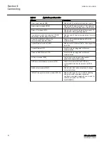
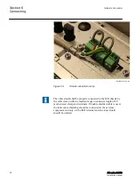
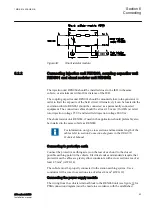
WARNING! USE EXTREME CAUTION!
Dangerously high
voltages might be present on this equipment, especially on the plate
with resistors. De-energize the primary object protected with this
equipment before connecting or disconnecting wiring or performing
any maintenance. The plate with resistors should be provided with a
protective cover, mounted in a separate box or in a locked cubicle.
National law and standards shall be followed.
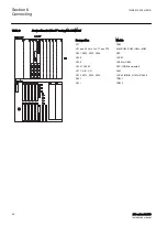
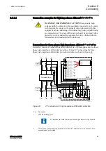
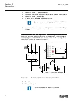
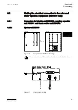
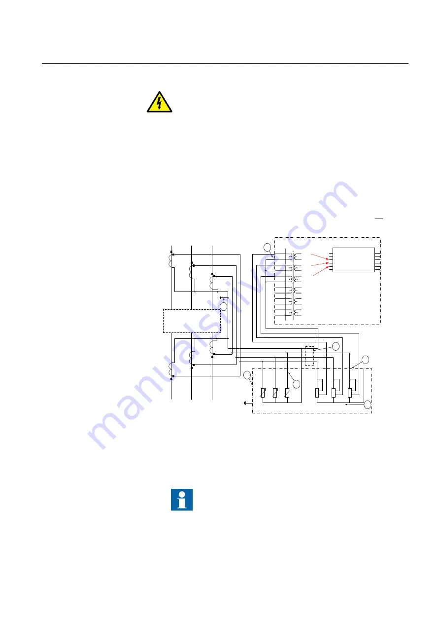
Connections for three-phase high impedance differential protection
GUID-C12CCAAF-5AE5-4A9C-AC9C-F56A66FD2C14 v8
Generator, reactor or busbar differential protection is a typical application for three-
phase high impedance differential protection. Typical CT connections for three-
phase high impedance differential protection scheme are shown in figure
.
L1
(A)
L2
(B)
L3
(C)
Protected Object
CT 1200/1
Star/Wye
Connected
L1
(A)
L2
(B)
L3
(C)
CT 1200/1
Star/Wye
Connected
7
8
9
1
0
1
1
1
2
1
2
3
4
5
6
AI01
(I)
AI02
(I)
AI03
(I)
AI04
(I)
AI05
(I)
AI06
(I)
7
6
X1
R
4
R
5
R
6
1
2
1
2
1
2
11
12
13
14
U
U
U
R
1
1
3
4
2
1
3
R
2
2
4
1
3
R
3
2
4
1
2
3
4
5
6 7
L1 (A)
L2 (B)
L3 (C)
N
3-Ph Plate with Metrosils and Resistors
2
3
5
4
X
X
L1 (A)
L2 (B)
L3 (C)
N
1
IED
IEC07000193-5-en.vsdx
SMAI2
BLOCK
REVROT
^GRP2L1
^GRP2L2
^GRP2L3
^GRP2N
G2AI3P
G2AI1
G2AI2
G2AI3
G2AI4
G2N
IEC07000193 V5 EN-US
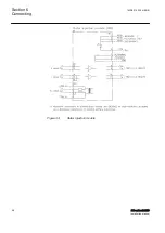
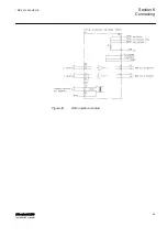
Figure 24:
CT connections for high impedance differential protection
Pos
Description
1
Scheme earthing point
It is important to insure that only one earthing point exist in this scheme.
2
Three-phase plate with setting resistors and metrosils. Protective earth is a separate 4 mm
screw terminal on the plate.
1MRK 514 026-UEN B
Section 6
Connecting
670 series 2.2 IEC
49
Installation manual
Summary of Contents for Relion 670 series
Page 1: ...RELION 670 SERIES 670 series Version 2 2 IEC Installation manual ...
Page 2: ......
Page 10: ...4 ...
Page 18: ...12 ...
Page 24: ...18 ...
Page 88: ...82 ...
Page 100: ...94 ...
Page 110: ...104 ...
Page 111: ...105 ...


