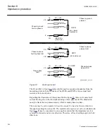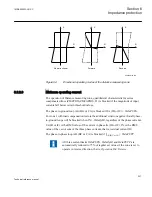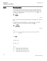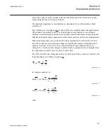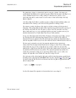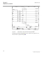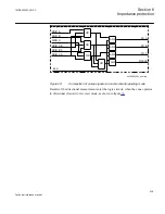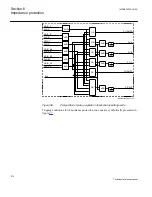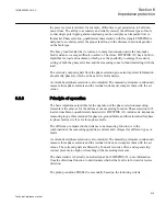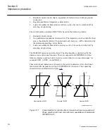
The polarizing voltage is a memorized positive sequence voltage. The memory is
continuously synchronized via a positive sequence filter. The memory is starting to run
freely instantaneously when a voltage change is detected in any phase. A non-
directional impedance measurement is used to detect a fault and identify the faulty
phase or phases.
At a three phase fault when no positive sequence voltage remains (all three phases are
disconnected) the memory is used for direction polarization during 100 ms.
The memory predicts the phase of the positive sequence voltage with the pre-fault
frequency. This extrapolation is made with a high accuracy and it is not the accuracy of
the memory that limits the time the memory can be used. The network is at a three
phase fault under way to a new equilibrium and the post-fault condition can only be
predicted accurately for a limited time from the pre-fault condition.
In case of a three phase fault after 100 ms the phase of the memorized voltage can not
be relied upon and the directional measurement has to be blocked. The achieved
direction criteria are sealed-in when the directional measurement is blocked and kept
until the impedance fault criteria is reset (the direction is stored until the fault is cleared).
This memory control allows in the time domain unlimited correct directional
measurement for all unsymmetrical faults also at voltage reversal. Only at three phase
fault within the range of the set impedance reach of the criteria for control of the
polarization voltage the memory has to be used and the measurement is limited to 100
ms and thereafter the direction is sealed-in. The special impedance measurement to
control the polarization voltage is set separately and has only to cover (with some
margin) the impedance to fault that can cause the voltage reversal.
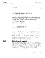
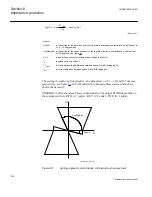
The evaluation of the directionality takes place in Directional impedance quadrilateral,
including series compensation (ZDSRDIR,21D) function. Equation
are used to classify that the fault is in forward direction for phase-to-ground fault and
phase-to-phase fault.
1
a g
Re
AM
A
V
AngDir
n
AngNeg
s
I
-
<
<
EQUATION2005 V2 EN
(Equation 22)
For the AB element, the equation in forward direction is according to:
1MRK505222-UUS C
Section 6
Impedance protection
205
Technical reference manual
Summary of Contents for Relion 670 series
Page 1: ...Relion 670 series Line differential protection RED670 ANSI Technical reference manual...
Page 2: ......
Page 40: ...34...
Page 50: ...44...
Page 60: ...54...
Page 126: ...120...
Page 384: ...378...
Page 496: ...490...
Page 556: ...550...
Page 602: ...596...
Page 620: ...614...
Page 794: ...788...
Page 864: ...858...
Page 988: ...982...
Page 998: ...992...
Page 1084: ...1078...
Page 1164: ...1158...
Page 1168: ...1162...
Page 1220: ...1214...
Page 1230: ...1224...
Page 1231: ...1225...

