0
3 I
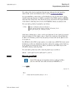
0.5
IMinPUPG
× ³
×
EQUATION2108-ANSI V1 EN
(Equation 27)
0
0
3
_
3
max
100
I Enable PG
I
Iph
×
³
×
EQUATION1812-ANSI V1 EN
(Equation 28)
where:
IMinPUPG
is the minimum operation current for forward zones
3I
0
Enable_PG is the setting for the minimum residual current needed to enable operation in the phase-to-
ground fault loops (in %).
Iphmax
is the maximum phase current in any of three phases.
6.3.3.2
Phase-to-phase fault
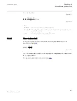
For a phase-to-phase fault, the measured impedance by FDPSPDIS (21) will be
according to equation
2
Vm Vn
ZPHS
In
-
=
- ×
EQUATION1813-ANSI V1 EN
(Equation 29)
Vm is the leading phase voltage, Vn the lagging phase voltage and In the phase current
in the lagging phase n.
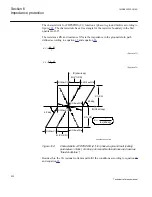
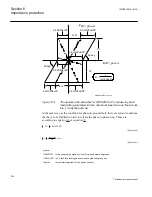
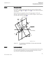
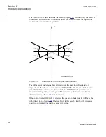
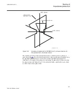
The operation characteristic is shown in figure
.
1MRK505222-UUS C
Section 6
Impedance protection
223
Technical reference manual
Summary of Contents for Relion 670 series
Page 1: ...Relion 670 series Line differential protection RED670 ANSI Technical reference manual...
Page 2: ......
Page 40: ...34...
Page 50: ...44...
Page 60: ...54...
Page 126: ...120...
Page 384: ...378...
Page 496: ...490...
Page 556: ...550...
Page 602: ...596...
Page 620: ...614...
Page 794: ...788...
Page 864: ...858...
Page 988: ...982...
Page 998: ...992...
Page 1084: ...1078...
Page 1164: ...1158...
Page 1168: ...1162...
Page 1220: ...1214...
Page 1230: ...1224...
Page 1231: ...1225...

