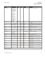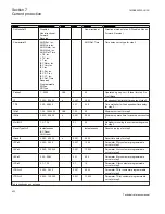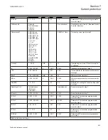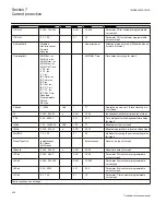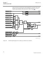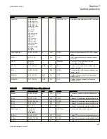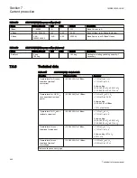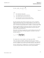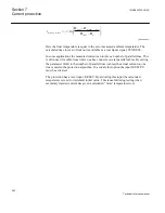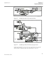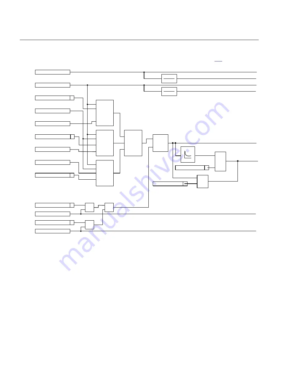
When the function is activated binary output signal PUVN is activated. If the output
signals are active after the set delay
tVNNonDir
TRIP and TRUN are activated. A
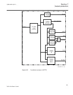
simplified logical diagram of the total function is shown in figure
en06000653_ansi.vsd
INNonDirPU
UN_PU
OpMODE=INcosPhi
Pickup_N
INCosPhiPU
OpMODE=INVNCosPhi
INVNCosPhiPU
Phi in RCA +- ROA
OpMODE=IN and Phi
DirMode = Forw
Forw
DirMode = Rev
Rev
PUNDIN
TRNDIN
PUVN
TRVN
AND
AND
AND
OR
AND
AND
AND
OR
PUDIRIN
PUFW
PUREV
0 - t
0 - t
0
0
TimeChar = DefTime
TRDIRIN
AND
SN
t
TimeChar = InvTime
AND
ANSI06000653 V1 EN
Figure 223:
Simplified logical diagram of the sensitive ground-fault current protection
Section 7
1MRK505222-UUS C
Current protection
444
Technical reference manual
Summary of Contents for Relion 670 series
Page 1: ...Relion 670 series Line differential protection RED670 ANSI Technical reference manual...
Page 2: ......
Page 40: ...34...
Page 50: ...44...
Page 60: ...54...
Page 126: ...120...
Page 384: ...378...
Page 496: ...490...
Page 556: ...550...
Page 602: ...596...
Page 620: ...614...
Page 794: ...788...
Page 864: ...858...
Page 988: ...982...
Page 998: ...992...
Page 1084: ...1078...
Page 1164: ...1158...
Page 1168: ...1162...
Page 1220: ...1214...
Page 1230: ...1224...
Page 1231: ...1225...


