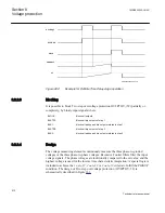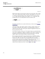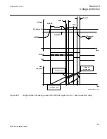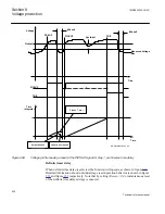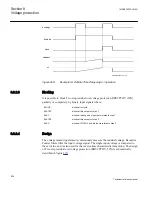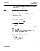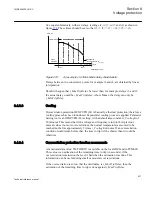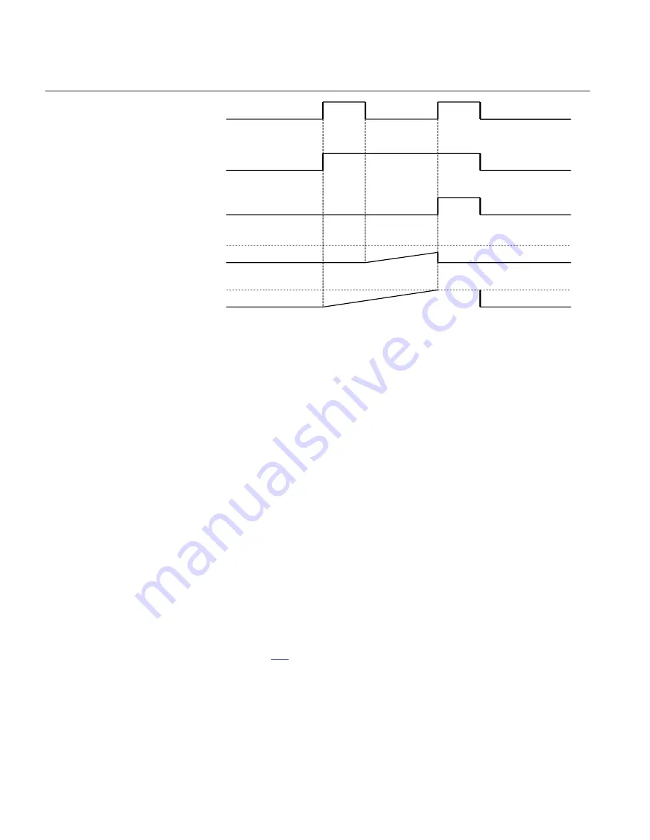
Pickup1
PICKUP
TRIP
tReset1
t1
ANSI10000038-2-en.vsd
ANSI10000038 V2 EN
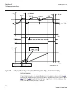
Figure 269:
Example for Definite Time Delay stage 1 operation
8.3.2.3
Blocking
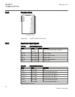
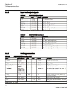
It is possible to block Two step residual overvoltage protection ROV2PTOV (59N)
partially or completely, by binary input signals where:
BLOCK:
blocks all outputs
BLKTR1:
blocks all trip outputs of step 1
BLK1:
blocks all pickup and trip outputs related to step 1
BLKTR2:
blocks all trip outputs of step 2
BLK2:
blocks all PICKUP and trip inputs related to step 2
8.3.2.4
Design
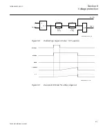
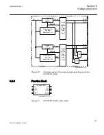
The voltage measuring elements continuously measure the residual voltage. Recursive
Fourier filters filter the input voltage signal. The single input voltage is compared to
the set value, and is also used for the inverse time characteristic integration. The design
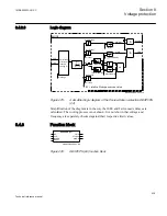
of Two step residual overvoltage protection (ROV2PTOV, 59N) is schematically
described in figure
Section 8
1MRK505222-UUS C
Voltage protection
524
Technical reference manual
Summary of Contents for Relion 670 series
Page 1: ...Relion 670 series Line differential protection RED670 ANSI Technical reference manual...
Page 2: ......
Page 40: ...34...
Page 50: ...44...
Page 60: ...54...
Page 126: ...120...
Page 384: ...378...
Page 496: ...490...
Page 556: ...550...
Page 602: ...596...
Page 620: ...614...
Page 794: ...788...
Page 864: ...858...
Page 988: ...982...
Page 998: ...992...
Page 1084: ...1078...
Page 1164: ...1158...
Page 1168: ...1162...
Page 1220: ...1214...
Page 1230: ...1224...
Page 1231: ...1225...

