E
f
fn
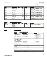
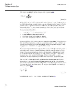
Pickup1
£
ANSIEQUATION2297 V2 EN
(Equation 138)
where:
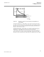
Pickup1 is the maximum continuously allowed voltage at no load, and rated frequency.
Pickup1
is a setting parameter. The setting range is 100% to 180%. If the user does not
know exactly what to set, then the default value for
Pickup1
= 110 % given by the IEC
60076-1 standard shall be used.
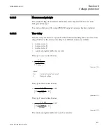
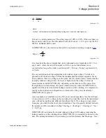
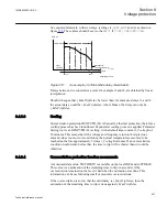
In OEXPVPH (24), the relative excitation M is expressed according to equation
.
( )
E f
M p.u. =
Vn fn
ANSIEQUATION2299 V1 EN
(Equation 139)
It is clear from the above formula that, for an unloaded power transformer, M = 1 for
any E and f, where the ratio E/f is equal to Vn/fn. A power transformer is not
overexcited as long as the relative excitation is M ≤
Pickup1
,
Pickup1
expressed in %
of Vn/fn.
The overexcitation protection algorithm is fed with an input voltage V which is in
general not the induced voltage E from the fundamental transformer equation. For no
load condition, these two voltages are the same, but for a loaded power transformer the
internally induced voltage E may be lower or higher than the voltage V which is
measured and fed to OEXPVPH (24), depending on the direction of the power flow
through the power transformer, the power transformer side where OEXPVPH (24) is
applied, and the power transformer leakage reactance of the winding. It is important to
specify in the application configuration on which side of the power transformer
OEXPVPH (24) is placed.
As an example, at a transformer with a 15% short circuit impedance Xsc, the full load,
0.8 power factor, 105% voltage on the load side, the actual flux level in the transformer
core, will not be significantly different from that at the 110% voltage, no load, rated
frequency, provided that the short circuit impedance X can be equally divided between
the primary and the secondary winding:
XLeakage
=
XLeakage1
=
XLeakage2
= Xsc /
2 = 0.075 pu.
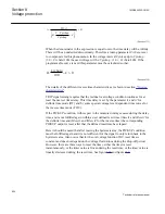
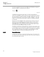
OEXPVPH (24) calculates the internal induced voltage E if
XLeakage
(meaning the
leakage reactance of the winding where OEXPVPH (24) is connected) is known to the
user. The assumption taken for two-winding power transformers that
XLeakage
= Xsc /
1MRK505222-UUS C
Section 8
Voltage protection
531
Technical reference manual
Summary of Contents for Relion 670 series
Page 1: ...Relion 670 series Line differential protection RED670 ANSI Technical reference manual...
Page 2: ......
Page 40: ...34...
Page 50: ...44...
Page 60: ...54...
Page 126: ...120...
Page 384: ...378...
Page 496: ...490...
Page 556: ...550...
Page 602: ...596...
Page 620: ...614...
Page 794: ...788...
Page 864: ...858...
Page 988: ...982...
Page 998: ...992...
Page 1084: ...1078...
Page 1164: ...1158...
Page 1168: ...1162...
Page 1220: ...1214...
Page 1230: ...1224...
Page 1231: ...1225...

