9.1.2.3
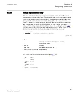
Voltage dependent time delay
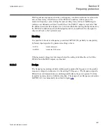
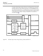
Since the fundamental frequency in a power system is the same all over the system,
except some deviations during power oscillations, another criterion is needed to decide,
where to take actions, based on low frequency. In many applications the voltage level
is very suitable, and in most cases is load shedding preferable in areas with low
voltage. Therefore, a voltage dependent time delay has been introduced, to make sure
that load shedding, or other actions, take place at the right location. At constant
voltage, V, the voltage dependent time delay is calculated according to equation
At non-constant voltage, the actual time delay is integrated in a similar way as for the
inverse time characteristic for the undervoltage and overvoltage functions.
(
)
_
_
_
Exponent
V VMin
t
t MaxTripDelay t MinTripDelay
t MinTripDelay
VNom VMin
-
=
×
-
+
-
é
ù
ê
ú
ë
û
EQUATION1559 V1 EN
(Equation 147)
where:
t
is the voltage dependent time delay (at constant voltage),
V
is the measured voltage
Exponent
is a setting,
VMin, VNom
are voltage settings corresponding to
t_MaxTripDelay, t_MinTripDelay are time settings.
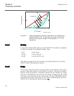
The inverse time characteristics are shown in figure
VMin
= 90%
= 100%
t_MaxTrip
Delay
= 1.0 s
t_MinTripD
elay
= 0.0 s
Exponent
= 0, 1, 2, 3 and 4
1MRK505222-UUS C
Section 9
Frequency protection
553
Technical reference manual
Summary of Contents for Relion 670 series
Page 1: ...Relion 670 series Line differential protection RED670 ANSI Technical reference manual...
Page 2: ......
Page 40: ...34...
Page 50: ...44...
Page 60: ...54...
Page 126: ...120...
Page 384: ...378...
Page 496: ...490...
Page 556: ...550...
Page 602: ...596...
Page 620: ...614...
Page 794: ...788...
Page 864: ...858...
Page 988: ...982...
Page 998: ...992...
Page 1084: ...1078...
Page 1164: ...1158...
Page 1168: ...1162...
Page 1220: ...1214...
Page 1230: ...1224...
Page 1231: ...1225...

