


For the disconnector positions it is advisable to use (NO) a and (NC) b type contacts to
supply Disconnector Open and Closed positions but, it is also possible to use an
inverter for one of the positions.
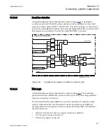
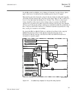
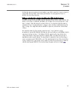
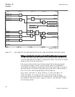
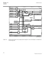
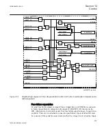
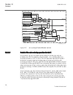
Voltage selection for a single circuit breaker with double busbars
This function uses the binary input from the disconnectors auxiliary contacts BUS1_OP-
BUS1_CL for Bus 1, and BUS2_OP-BUS2_CL for Bus 2 to select between bus 1 and
bus 2 voltages. If the disconnector connected to bus 1 is closed and the disconnector
connected to bus 2 is opened the bus 1 voltage is used. All other combinations use the
bus 2 voltage. The outputs B1SEL and B2SEL respectively indicate the selected Bus
voltage.
The function checks the fuse-failure signals for bus 1, bus 2 and line voltage
transformers. Inputs VB1OK-VB1FF supervise the fuse for Bus 1 and VB2OK-VB2FF
supervises the fuse for Bus 2. VL1OK and VL1FF supervises the fuse for the Line
voltage transformer. The inputs fail (FF) or healthy (OK) can alternatively be used
dependent on the available signal. If a fuse-failure is detected in the selected voltage
source an output signal VSELFAIL is set. This output signal is true if the selected bus
or line voltages have a fuse failure. This output as well as the function can be blocked
with the input signal BLOCK. The function logic diagram is shown in figure
1MRK505222-UUS C
Section 12
Control
621
Technical reference manual
Summary of Contents for Relion 670 series
Page 1: ...Relion 670 series Line differential protection RED670 ANSI Technical reference manual...
Page 2: ......
Page 40: ...34...
Page 50: ...44...
Page 60: ...54...
Page 126: ...120...
Page 384: ...378...
Page 496: ...490...
Page 556: ...550...
Page 602: ...596...
Page 620: ...614...
Page 794: ...788...
Page 864: ...858...
Page 988: ...982...
Page 998: ...992...
Page 1084: ...1078...
Page 1164: ...1158...
Page 1168: ...1162...
Page 1220: ...1214...
Page 1230: ...1224...
Page 1231: ...1225...


